Chapter 5. Air Traffic ProceduresSection 1. Preflight5-1-1. Preflight Preparation a. Every pilot is urged to receive a preflight briefing and to file a flight plan. This briefing should consist of the latest or most current weather, airport, and en route NAVAID information. Briefing service may be obtained from an FSS either by telephone, by radio when airborne, or by a personal visit to the station. Pilots with a current medical certificate in the 48 contiguous States may access Lockheed Martin Flight Services or the Direct User Access Terminal System (DUATS) via the internet. Lockheed Martin Flight Services and DUATS will provide preflight weather data and allow pilots to file domestic VFR or IFR flight plans.
REFERENCE- NOTE- b. The information required by the FAA to process flight plans is contained on FAA Form 7233-1, Flight Plan, or FAA Form 7233-4, International Flight Plan. The forms are available at all flight service stations. Additional copies will be provided on request.
REFERENCE- c. Consult an FSS, Lockheed Martin Flight Services, or DUATS for preflight weather briefing. d. FSSs are required to advise of pertinent NOTAMs if a standard briefing is requested, but if they are overlooked, don't hesitate to remind the specialist that you have not received NOTAM information. NOTE-
REFERENCE- e. Pilots are urged to use only the latest issue of aeronautical charts in planning and conducting flight operations. Aeronautical charts are revised and reissued on a regular scheduled basis to ensure that depicted data are current and reliable. In the conterminous U.S., Sectional Charts are updated every 6 months, IFR En Route Charts every 56 days, and amendments to civil IFR Approach Charts are accomplished on a 56-day cycle with a change notice volume issued on the 28-day midcycle. Charts that have been superseded by those of a more recent date may contain obsolete or incomplete flight information.
REFERENCE- f. When requesting a preflight briefing, identify yourself as a pilot and provide the following: 1. Type of flight planned; e.g., VFR or IFR. 2. Aircraft's number or pilot's name. 3. Aircraft type. 4. Departure Airport. 5. Route of flight. 6. Destination. 7. Flight altitude(s). 8. ETD and ETE. g. Prior to conducting a briefing, briefers are required to have the background information listed above so that they may tailor the briefing to the needs of the proposed flight. The objective is to communicate a "picture" of meteorological and aeronautical information necessary for the conduct of a safe and efficient flight. Briefers use all available weather and aeronautical information to summarize data applicable to the proposed flight. They do not read weather reports and forecasts verbatim unless specifically requested by the pilot. FSS briefers do not provide FDC NOTAM information for special instrument approach procedures unless specifically asked. Pilots authorized by the FAA to use special instrument approach procedures must specifically request FDC NOTAM information for these procedures. Pilots who receive the information electronically will receive NOTAMs for special IAPs automatically.
REFERENCE- h. FAA by 14 CFR Part 93, Subpart K, has designated High Density Traffic Airports (HDTAs) and has prescribed air traffic rules and requirements for operating aircraft (excluding helicopter operations) to and from these airports.
REFERENCE- i. In addition to the filing of a flight plan, if the flight will traverse or land in one or more foreign countries, it is particularly important that pilots leave a complete itinerary with someone directly concerned and keep that person advised of the flight's progress. If serious doubt arises as to the safety of the flight, that person should first contact the FSS.
REFERENCE- j. Pilots operating under provisions of 14 CFR Part 135 on a domestic flight and not having an FAA assigned 3-letter designator, are urged to prefix the normal registration (N) number with the letter "T" on flight plan filing; e.g., TN1234B.
REFERENCE- 5-1-2. Follow IFR Procedures Even When Operating VFR a. To maintain IFR proficiency, pilots are urged to practice IFR procedures whenever possible, even when operating VFR. Some suggested practices include: 1. Obtain a complete preflight and weather briefing. Check the NOTAMs. 2. File a flight plan. This is an excellent low cost insurance policy. The cost is the time it takes to fill it out. The insurance includes the knowledge that someone will be looking for you if you become overdue at your destination. 3. Use current charts. 4. Use the navigation aids. Practice maintaining a good course-keep the needle centered. 5. Maintain a constant altitude which is appropriate for the direction of flight. 6. Estimate en route position times. 7. Make accurate and frequent position reports to the FSSs along your route of flight. b. Simulated IFR flight is recommended (under the hood); however, pilots are cautioned to review and adhere to the requirements specified in 14 CFR Section 91.109 before and during such flight. c. When flying VFR at night, in addition to the altitude appropriate for the direction of flight, pilots should maintain an altitude which is at or above the minimum en route altitude as shown on charts. This is especially true in mountainous terrain, where there is usually very little ground reference. Do not depend on your eyes alone to avoid rising unlighted terrain, or even lighted obstructions such as TV towers. 5-1-3. Notice to Airmen (NOTAM) System a. Time-critical aeronautical information which is of either a temporary nature or not sufficiently known in advance to permit publication on aeronautical charts or in other operational publications receives immediate dissemination via the National NOTAM System. NOTE- 2. NOTAM information is transmitted using standard contractions to reduce transmission time. See TBL 5-1-2 for a listing of the most commonly used contractions. For a complete listing, see FAA Order 7340.2, Contractions. b. NOTAM information is classified into five categories. These are NOTAM (D) or distant, Flight Data Center (FDC) NOTAMs, Pointer NOTAMs, Special Activity Airspace (SAA), and Military NOTAMs. 1. NOTAM (D) information is disseminated for all navigational facilities that are part of the National Airspace System (NAS), all public use airports, seaplane bases, and heliports listed in the Airport/Facility Directory (A/FD). The complete file of all NOTAM (D) information is maintained in a computer database at the Weather Message Switching Center (WMSC), located in Atlanta, Georgia. This category of information is distributed automatically via Service A telecommunications system. Air traffic facilities, primarily FSSs, with Service A capability have access to the entire WMSC database of NOTAMs. These NOTAMs remain available via Service A for the duration of their validity or until published. Once published, the NOTAM data is deleted from the system. NOTAM (D) information includes such data as taxiway closures, personnel and equipment near or crossing runways, and airport lighting aids that do not affect instrument approach criteria, such as VASI. All NOTAM Ds must have one of the following keywords listed in TBL 5-1-1 as the first part of the text after the location identifier: 2. FDC NOTAMs. On those occasions when it becomes necessary to disseminate information which is regulatory in nature, the National Flight Data Center (NFDC), in Washington, DC, will issue an FDC NOTAM. FDC NOTAMs contain such things as amendments to published IAPs and other current aeronautical charts. They are also used to advertise temporary flight restrictions caused by such things as natural disasters or large-scale public events that may generate a congestion of air traffic over a site. NOTE- 2. NOTAM data may not always be current due to the changeable nature of national airspace system components, delays inherent in processing information, and occasional temporary outages of the U.S. NOTAM system. While en route, pilots should contact FSSs and obtain updated information for their route of flight and destination. 3. Pointer NOTAMs. NOTAMs issued by a flight service station to highlight or point out another NOTAM, such as an FDC or NOTAM (D) NOTAM. This type of NOTAM will assist users in cross-referencing important information that may not be found under an airport or NAVAID identifier. Keywords in pointer NOTAMs must match the keywords in the NOTAM that is being pointed out. The keyword in pointer NOTAMs related to Temporary Flight Restrictions (TFR) must be AIRSPACE. 4. SAA NOTAMs. These NOTAMs are issued when Special Activity Airspace will be active outside the published schedule times and when required by the published schedule. Pilots and other users are still responsible to check published schedule times for Special Activity Airspace as well as any NOTAMs for that airspace. 5. Military NOTAMs. NOTAMs pertaining to U.S. Air Force, Army, Marine, and Navy navigational aids/airports that are part of the NAS. c. Notices to Airmen Publication (NTAP). The NTAP is published by Mission Support Services, ATC Products and Publications, every 28 days. Data of a permanent nature can be published in the NTAP as an interim step between publication cycles of the A/FD and aeronautical charts. The NTAP is divided into four parts: 1. Notices in part 1 are provided by ATC Products and Publications. This part contains selected FDC NOTAMs that are expected to be in effect on the effective date of the publication. This part is divided into three sections: (a) Section 1, Airway NOTAMs, reflects airway changes that fall within an ARTCC's airspace. (b) Section 2, Procedural NOTAMs. (c) Section 3, General NOTAMs, contains NOTAMs that are general in nature and not tied to a specific airport/facility (for example, flight advisories and restrictions, open duration special security instructions, and special flight rules area). 2. Part 2, provided by NFDC, contains Part 95 Revisions, Revisions to Minimum En Route IFR Altitudes and Changeover Points. 3. Part 3, International NOTAMs, is divided into two sections: (a) Section 1, International Flight Prohibitions, Potential Hostile Situations, and Foreign Notices. (b) Section 2, International Oceanic Airspace Notices. 4. Part 4, Graphic Notices, compiled by ATC Products and Publications from data provided by FAA service area offices and other lines of business, contains special notices and graphics pertaining to almost every aspect of aviation such as: military training areas, large scale sporting events, air show information, Special Traffic Management Programs (STMP), and airport-specific information. This part is comprised of 6 sections: General, Special Military Operations, Airport and Facility Notices, Major Sporting and Entertainment Events, Airshows, and Special Notices.
TBL 5-1-1
NOTE- 2. ** Other Aeronautical Information is that which is received from any authorized source that may be beneficial to aircraft operations and does not meet defined NOTAM criteria. Any such NOTAM will be prefaced with "(O)" as the keyword following the location identifier.
TBL 5-1-2
5-1-4. Flight Plan - VFR Flights a. Except for operations in or penetrating a Coastal or Domestic ADIZ or DEWIZ a flight plan is not required for VFR flight.
REFERENCE- b. It is strongly recommended that a flight plan (for a VFR flight) be filed with an FAA FSS. This will ensure that you receive VFR Search and Rescue Protection.
REFERENCE- c. To obtain maximum benefits from the flight plan program, flight plans should be filed directly with the nearest FSS. For your convenience, FSSs provide aeronautical and meteorological briefings while accepting flight plans. Radio may be used to file if no other means are available. NOTE- d. When a "stopover" flight is anticipated, it is recommended that a separate flight plan be filed for each "leg" when the stop is expected to be more than 1 hour duration. e. Pilots are encouraged to give their departure times directly to the FSS serving the departure airport or as otherwise indicated by the FSS when the flight plan is filed. This will ensure more efficient flight plan service and permit the FSS to advise you of significant changes in aeronautical facilities or meteorological conditions. When a VFR flight plan is filed, it will be held by the FSS until 1 hour after the proposed departure time unless: 1. The actual departure time is received. 2. A revised proposed departure time is received. 3. At a time of filing, the FSS is informed that the proposed departure time will be met, but actual time cannot be given because of inadequate communications (assumed departures). f. On pilot's request, at a location having an active tower, the aircraft identification will be forwarded by the tower to the FSS for reporting the actual departure time. This procedure should be avoided at busy airports. g. Although position reports are not required for VFR flight plans, periodic reports to FAA FSSs along the route are good practice. Such contacts permit significant information to be passed to the transiting aircraft and also serve to check the progress of the flight should it be necessary for any reason to locate the aircraft. EXAMPLE- 2. Cherokee 5133J, over Oklahoma City at (time), Shreveport to Denver, no flight plan. h. Pilots not operating on an IFR flight plan and when in level cruising flight, are cautioned to conform with VFR cruising altitudes appropriate to the direction of flight. i. When filing VFR flight plans, indicate aircraft equipment capabilities by appending the appropriate suffix to aircraft type in the same manner as that prescribed for IFR flight.
REFERENCE- j. Under some circumstances, ATC computer tapes can be useful in constructing the radar history of a downed or crashed aircraft. In each case, knowledge of the aircraft's transponder equipment is necessary in determining whether or not such computer tapes might prove effective.
FIG 5-1-1
|
|||||||||||||||||||||||||||||||||||||||||||||||||||||||||||||||||||||||||||||||||||||||||||||||||||||||||||||||||||||||||||||||||||||||||||||||||||||||||||||||||||||||||||||||||||||||||||||||||||||||||||||||||||||||||||||||||||||||||||||||||||||||||||||||||||||||||||||||||||||||||||||||||||||||||||||||||||||||||||||||||||||||||||||||||||||||||||||||||||||||||||||||||||||||||||||||||||||||||||||||||||||||||||||||||||||||||||||||||||||||||||||||||||||||||||||||||||||||||||||||||||||||||||||||||||||||||||||||||||||||||||||||||||||||||||||||||||||||||||||||||||||||||||||||||||||||||||||||||||||||||||||||||||||||||||||||||||||||||||||||||||||||||||||||||||||||||
|
|
Navigation Capability |
Transponder Capability |
Suffix |
|
RVSM |
No GNSS, No RNAV |
Transponder with Mode C |
/W |
|
RNAV, No GNSS |
Transponder with Mode C |
/Z |
|
|
GNSS |
Transponder with Mode C |
/L |
|
|
|
|||
|
No RVSM |
|
No Transponder |
/X |
|
Transponder with no Mode C |
/T |
||
|
Transponder with Mode C |
/U |
||
|
|
No Transponder |
/D |
|
|
Transponder with no Mode C |
/B |
||
|
Transponder with Mode C |
/A |
||
|
|
No Transponder |
/M |
|
|
Transponder with no Mode C |
/N |
||
|
Transponder with Mode C |
/P |
||
|
|
No Transponder |
/Y |
|
|
Transponder with no Mode C |
/C |
||
|
Transponder with Mode C |
/I |
||
|
|
No Transponder |
/V |
|
|
Transponder with no Mode C |
/S |
||
|
Transponder with Mode C |
/G |
||
b. Airways and Jet Routes Depiction on Flight Plan
1. It is vitally important that the route of flight be accurately and completely described in the flight plan. To simplify definition of the proposed route, and to facilitate ATC, pilots are requested to file via airways or jet routes established for use at the altitude or flight level planned.
2. If flight is to be conducted via designated airways or jet routes, describe the route by indicating the type and number designators of the airway(s) or jet route(s) requested. If more than one airway or jet route is to be used, clearly indicate points of transition. If the transition is made at an unnamed intersection, show the next succeeding NAVAID or named intersection on the intended route and the complete route from that point. Reporting points may be identified by using authorized name/code as depicted on appropriate aeronautical charts. The following two examples illustrate the need to specify the transition point when two routes share more than one transition fix.
EXAMPLE-
1. ALB J37 BUMPY J14 BHM
Spelled out: from Albany, New York, via Jet Route 37 transitioning to Jet Route
14 at BUMPY intersection, thence via Jet Route 14 to Birmingham, Alabama.
2. ALB J37 ENO
J14 BHM
Spelled out: from Albany, New York, via Jet Route 37 transitioning to Jet Route
14 at Smyrna VORTAC (ENO) thence via Jet Route 14 to Birmingham, Alabama.
3. The route of flight may also be described by naming the reporting points or NAVAIDs over which the flight will pass, provided the points named are established for use at the altitude or flight level planned.
EXAMPLE-
BWI V44 SWANN V433 DQO
Spelled out: from Baltimore-Washington International, via Victor 44 to Swann
intersection, transitioning to Victor 433 at Swann, thence via Victor 433 to Dupont.
4. When the route of flight is defined by named reporting points, whether alone or in combination with airways or jet routes, and the navigational aids (VOR, VORTAC, TACAN, NDB) to be used for the flight are a combination of different types of aids, enough information should be included to clearly indicate the route requested.
EXAMPLE-
LAX J5 LKV J3 GEG YXC FL 330 J500 VLR J515 YWG
Spelled out: from Los Angeles International via Jet Route 5 Lakeview, Jet Route
3 Spokane, direct Cranbrook, British Columbia VOR/DME, Flight Level 330 Jet
Route 500 to Langruth, Manitoba VORTAC, Jet Route 515 to Winnepeg, Manitoba.
5. When filing IFR, it is to the pilot's advantage to file a preferred route.
REFERENCE-
Preferred IFR Routes are described and tabulated in the Airport/Facility
Directory.
6. ATC may issue a SID or a STAR, as appropriate.
REFERENCE-
AIM, Instrument Departure Procedures (DP) - Obstacle Departure Procedures (ODP)
and Standard Instrument Departures (SID), Paragraph
5-2-8.
AIM, Standard Terminal Arrival (STAR), Area Navigation (RNAV) STAR, and Flight
Management System Procedures (FMSP) for Arrivals, Paragraph
5-4-1.
NOTE-
Pilots not desiring a SID or STAR should so indicate in the remarks section of
the flight plan as "no SID" or "no STAR."
c. Direct Flights
1. All or any portions of the route which will not be flown on the radials or courses of established airways or routes, such as direct route flights, must be defined by indicating the radio fixes over which the flight will pass. Fixes selected to define the route must be those over which the position of the aircraft can be accurately determined. Such fixes automatically become compulsory reporting points for the flight, unless advised otherwise by ATC. Only those navigational aids established for use in a particular structure; i.e., in the low or high structures, may be used to define the en route phase of a direct flight within that altitude structure.
2. The azimuth feature of VOR aids and that azimuth and distance (DME) features of VORTAC and TACAN aids are assigned certain frequency protected areas of airspace which are intended for application to established airway and route use, and to provide guidance for planning flights outside of established airways or routes. These areas of airspace are expressed in terms of cylindrical service volumes of specified dimensions called "class limits" or "categories."
REFERENCE-
AIM, Navigational Aid (NAVAID) Service Volumes, Paragraph
1-1-8.
3. An operational service volume has been established for each class in which adequate signal coverage and frequency protection can be assured. To facilitate use of VOR, VORTAC, or TACAN aids, consistent with their operational service volume limits, pilot use of such aids for defining a direct route of flight in controlled airspace should not exceed the following:
(a) Operations above FL 450 - Use aids not more than 200 NM apart. These aids are depicted on enroute high altitude charts.
(b) Operation off established routes from 18,000 feet MSL to FL 450 - Use aids not more than 260 NM apart. These aids are depicted on enroute high altitude charts.
(c) Operation off established airways below 18,000 feet MSL - Use aids not more than 80 NM apart. These aids are depicted on enroute low altitude charts.
(d) Operation off established airways between 14,500 feet MSL and 17,999 feet MSL in the conterminous U.S. - (H) facilities not more than 200 NM apart may be used.
4. Increasing use of self-contained airborne navigational systems which do not rely on the VOR/VORTAC/TACAN system has resulted in pilot requests for direct routes which exceed NAVAID service volume limits. These direct route requests will be approved only in a radar environment, with approval based on pilot responsibility for navigation on the authorized direct route. Radar flight following will be provided by ATC for ATC purposes.
5. At times, ATC will initiate a direct route in a radar environment which exceeds NAVAID service volume limits. In such cases ATC will provide radar monitoring and navigational assistance as necessary.
6. Airway or jet route numbers, appropriate to the stratum in which operation will be conducted, may also be included to describe portions of the route to be flown.
EXAMPLE-
MDW V262 BDF V10 BRL STJ SLN GCK
Spelled out: from Chicago Midway Airport via Victor 262 to Bradford, Victor 10
to Burlington, Iowa, direct St. Joseph, Missouri, direct Salina, Kansas, direct
Garden City, Kansas.
NOTE-
When route of flight is described by radio fixes, the pilot will be expected to
fly a direct course between the points named.
7. Pilots are reminded that they are responsible for adhering to obstruction clearance requirements on those segments of direct routes that are outside of controlled airspace. The MEAs and other altitudes shown on low altitude IFR enroute charts pertain to those route segments within controlled airspace, and those altitudes may not meet obstruction clearance criteria when operating off those routes.
d. Area Navigation (RNAV)
1. Random impromptu routes can only be approved in a radar environment. Factors that will be considered by ATC in approving random impromptu routes include the capability to provide radar monitoring and compatibility with traffic volume and flow. ATC will radar monitor each flight, however, navigation on the random impromptu route is the responsibility of the pilot.
2. Pilots of aircraft equipped with approved area navigation equipment may file for RNAV routes throughout the National Airspace System and may be filed for in accordance with the following procedures.
(a) File airport-to-airport flight plans.
(b) File the appropriate RNAV capability certification suffix in the flight plan.
(c) Plan the random route portion of the flight plan to begin and end over appropriate arrival and departure transition fixes or appropriate navigation aids for the altitude stratum within which the flight will be conducted. The use of normal preferred departure and arrival routes (DP/STAR), where established, is recommended.
(d) File route structure transitions to and from the random route portion of the flight.
(e) Define the random route by waypoints. File route description waypoints by using degree-distance fixes based on navigational aids which are appropriate for the altitude stratum.
(f) File a minimum of one route description waypoint for each ARTCC through whose area the random route will be flown. These waypoints must be located within 200 NM of the preceding center's boundary.
(g) File an additional route description waypoint for each turnpoint in the route.
(h) Plan additional route description waypoints as required to ensure accurate navigation via the filed route of flight. Navigation is the pilot's responsibility unless ATC assistance is requested.
(i) Plan the route of flight so as to avoid prohibited and restricted airspace by 3 NM unless permission has been obtained to operate in that airspace and the appropriate ATC facilities are advised.
NOTE-
To be approved for use in the National Airspace System, RNAV equipment must meet
the appropriate system availability, accuracy, and airworthiness standards. For
additional guidance on equipment requirements see AC 20-130, Airworthiness
Approval of Vertical Navigation (VNAV) Systems for use in the U.S. NAS and
Alaska, or AC 20-138, Airworthiness Approval of Global Positioning System (GPS)
Navigation Equipment for Use as a VFR and IFR Supplemental Navigation System.
For airborne navigation database, see AC 90-94, Guidelines for Using GPS
Equipment for IFR En Route and Terminal Operations and for Nonprecision
Instrument Approaches in the U.S. National Airspace System, Section 2.
3. Pilots of aircraft equipped with latitude/longitude coordinate navigation capability, independent of VOR/TACAN references, may file for random RNAV routes at and above FL 390 within the conterminous U.S. using the following procedures.
(a) File airport-to-airport flight plans prior to departure.
(b) File the appropriate RNAV capability certification suffix in the flight plan.
(c) Plan the random route portion of the flight to begin and end over published departure/arrival transition fixes or appropriate navigation aids for airports without published transition procedures. The use of preferred departure and arrival routes, such as DP and STAR where established, is recommended.
(d) Plan the route of flight so as to avoid prohibited and restricted airspace by 3 NM unless permission has been obtained to operate in that airspace and the appropriate ATC facility is advised.
(e) Define the route of flight after the departure fix, including each intermediate fix (turnpoint) and the arrival fix for the destination airport in terms of latitude/longitude coordinates plotted to the nearest minute or in terms of Navigation Reference System (NRS) waypoints. For latitude/longitude filing the arrival fix must be identified by both the latitude/longitude coordinates and a fix identifier.
EXAMPLE-
MIA1 SRQ2 3407/106153 3407/11546 TNP4
LAX 5
1 Departure airport.
2 Departure fix.
3 Intermediate fix (turning point).
4 Arrival fix.
5 Destination airport.
or
ORD1 IOW2 KP49G3 KD34U4 KL16O5
OAL6 MOD27
SFO8
1 Departure airport.
2 Transition fix (pitch point).
3 Minneapolis ARTCC waypoint.
4 Denver ARTCC Waypoint.
5 Los Angeles ARTCC waypoint (catch point).
6 Transition fix.
7 Arrival.
8 Destination airport.
(f) Record latitude/longitude coordinates by four figures describing latitude in degrees and minutes followed by a solidus and five figures describing longitude in degrees and minutes.
(g) File at FL 390 or above for the random RNAV portion of the flight.
(h) Fly all routes/route segments on Great Circle tracks.
(i) Make any inflight requests for random RNAV clearances or route amendments to an en route ATC facility.
e. Flight Plan Form- See FIG 5-1-2.
f. Explanation of IFR Flight Plan Items.
1. Block 1. Check the type flight plan. Check both the VFR and IFR blocks if composite VFR/IFR.
2. Block 2. Enter your complete aircraft identification including the prefix "N" if applicable.
3. Block 3. Enter the designator for the aircraft, followed by a slant(/), and the transponder or DME equipment code letter; e.g., C-182/U. Heavy aircraft, add prefix "H" to aircraft type; example: H/DC10/U. Consult an FSS briefer for any unknown elements.
FIG 5-1-2
FAA Flight Plan
Form 7233-1 (8-82)

4. Block 4. Enter your computed true airspeed (TAS).
NOTE-
If the average TAS changes plus or minus 5 percent or 10 knots, whichever is
greater, advise ATC.
5. Block 5. Enter the departure airport identifier code (or the airport name, city and state, if the identifier is unknown).
NOTE-
Use of identifier codes will expedite the processing of your flight plan.
6. Block 6. Enter the proposed departure time in Coordinated Universal Time (UTC) (Z). If airborne, specify the actual or proposed departure time as appropriate.
7. Block 7. Enter the requested en route altitude or flight level.
NOTE-
Enter only the initial requested altitude in this block. When more than one IFR
altitude or flight level is desired along the route of flight, it is best to
make a subsequent request direct to the controller.
8. Block 8. Define the route of flight by using NAVAID identifier codes (or names if the code is unknown), airways, jet routes, and waypoints (for RNAV).
NOTE-
Use NAVAIDs or waypoints to define direct routes and radials/bearings to define
other unpublished routes.
9. Block 9. Enter the destination airport identifier code (or name if the identifier is unknown).
10. Block 10. Enter your estimated time en route based on latest forecast winds.
11. Block 11. Enter only those remarks pertinent to ATC or to the clarification of other flight plan information, such as the appropriate radiotelephony (call sign) associated with the FAA-assigned three-letter company designator filed in Block 2, if the radiotelephony is new or has changed within the last 60 days. In cases where there is no three-letter designator but only an assigned radiotelephony or an assigned three-letter designator is used in a medical emergency, the radiotelephony must be included in the remarks field. Items of a personal nature are not accepted.
NOTE-
1. The pilot is responsible for knowing
when it is appropriate to file the radiotelephony in remarks under the 60-day
rule or when using FAA special radiotelephony assignments.
2. "DVRSN" should be placed in Block 11 only if the pilot/company is requesting priority handling to their original destination from ATC as a result of a diversion as defined in the Pilot/Controller Glossary.
3. Do not assume that remarks will be automatically transmitted to every controller. Specific ATC or en route requests should be made directly to the appropriate controller.
12. Block 12. Specify the fuel on board, computed from the departure point.
13. Block 13. Specify an alternate airport if desired or required, but do not include routing to the alternate airport.
14. Block 14. Enter the complete name, address, and telephone number of pilot-in-command, or in the case of a formation flight, the formation commander. Enter sufficient information to identify home base, airport, or operator.
NOTE-
This information would be essential in the event of search and rescue operation.
15. Block 15. Enter the total number of persons on board including crew.
16. Block 16. Enter the predominant colors.
NOTE-
Close IFR flight plans with tower, approach control, or ARTCC, or if unable,
with FSS. When landing at an airport with a functioning control tower, IFR
flight plans are automatically canceled.
g. The information transmitted to the ARTCC for IFR flight plans will consist of only flight plan blocks 2, 3, 4, 5, 6, 7, 8, 9, 10, and 11.
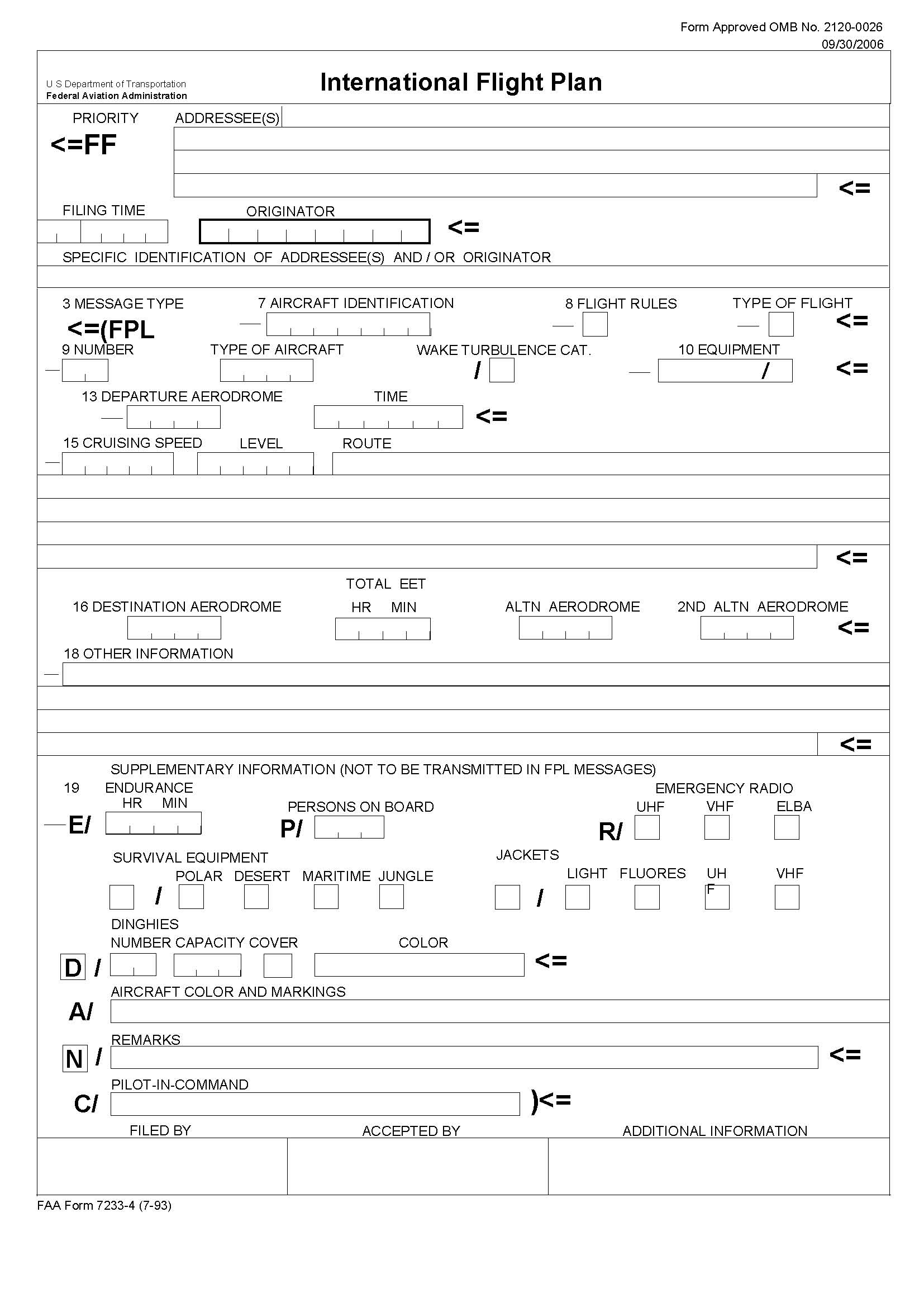
h. A description of the International Flight Plan Form is contained in the International Flight Information Manual (IFIM).
5-1-9. International Flight Plan (FAA Form 7233-4)- IFR Flights (For Domestic or International Flights)
a. General
Use of FAA Form 7233-4 is:
1. Mandatory for assignment of RNAV SIDs and STARs or other PBN routing,
2. Mandatory for all IFR flights that will depart U.S. domestic airspace, and
3. Recommended for domestic IFR flights.
NOTE-
1. An abbreviated description of FAA Form 7233-4 (International
Flight Plan) may be found in this section. A detailed description of FAA Form
7233-4 may be found on the FAA website at:
http://www.faa.gov/about/office_org/headquarters_offices/ato/service_units/
enroute/flight_plan_filing/
2. Filers utilizing FAA Form 7233-1 (Flight Plan) may not be eligible for assignment of RNAV SIDs and STARs. Filers desiring assignment of these procedures should file using FAA Form 7233-4, as described in this section.
3. When filing an IFR flight plan using FAA Form 7233-4, it is recommended that filers include all operable navigation, communication, and surveillance equipment capabilities by adding appropriate equipment qualifiers as shown in Tables 5-1-3 and 5-1-4. These equipment qualifiers should be filed in Item 10 of FAA Form 7233-4.
4. ATC issues clearances based on aircraft capabilities filed in Items 10 and 18 of FAA Form 7233-4. Operators should file all capabilities for which the aircraft and crew is certified, capable, and authorized. PBN/ capability should be filed as per paragraph 5-1-9 b 8 Items 18 (c) and (d).
b. Explanation of Items Filed in FAA Form 7233-4
Procedures and other information provided in this section are designed to assist operators using FAA Form 7233-4 to file IFR flight plans for flights that will be conducted entirely within U.S. domestic airspace. Requirements and procedures for operating outside U.S. domestic airspace may vary significantly from country to country. It is, therefore, recommended that operators planning flights outside U.S. domestic airspace become familiar with applicable international documents, including Aeronautical Information Publications (AIP); International Flight Information Manuals (IFIM); and ICAO Document 4444, Procedures for Air Navigation Services/Air Traffic Management, Appendix 2.
NOTE-
FAA Form 7233-4 is shown in FIG 5-1-3. The filer is
normally responsible for providing the information required in Items 3 through
19.
1. Item 7. Aircraft Identification. Insert the full registration number of the aircraft, or the approved FAA/ICAO company or organizational designator, followed by the flight number.
EXAMPLE-
N235RA, AAL3342, BONGO33
NOTE-
Callsigns filed in this item must begin with a letter followed by 1-6 additional
alphanumeric characters.
2. Item 8. Flight Rules and Type of Flight.
(a) Flight Rules. Insert the character "I" to indicate IFR
(b) Type of Flight. Insert one of the following letters to denote the type of flight:
(1) S if scheduled air service
(2) N if non-scheduled air transport operation
(3) G if general aviation
(4) M if military
(5) X if other than any of the defined categories above.
NOTE-
Type of flight is optional for flights that will be conducted entirely within
U.S. domestic airspace.
3. Item 9. Number, Type of Aircraft, and Wake Turbulence Category.
(a) Number. Insert the number of aircraft, if more than 1 (maximum 99).
(b) Type of Aircraft.
(1) Insert the appropriate designator as specified in ICAO Doc 8643, Aircraft Type Designators;
(2) Or, if no such designator has been assigned, or in the case of formation flights consisting of more than one type;
(3) Insert ZZZZ, and specify in Item 18, the (numbers and) type(s) of aircraft preceded by TYP/.
(c) Wake Turbulence Category. Insert an oblique stroke followed by one of the following letters to indicate the wake turbulence category of the aircraft:
(1) H - HEAVY, to indicate an aircraft type with a maximum certificated takeoff weight of 300,000 pounds (136 000 kg), or more;
(2) M - MEDIUM, to indicate an aircraft type with a maximum certificated takeoff weight of less than 300,000 pounds (136,000 kg), but more than 15,500 pounds (7,000 kg);
(3) L - LIGHT, to indicate an aircraft type with a maximum certificated takeoff weight of 15,500 pounds (7,000 kg) or less.
4. Item 10. Equipment
FIG 5-1-3
FAA International Flight Plan Form 7233-4 (9-06)
TBL 5-1-4
Aircraft COM, NAV, and Approach Equipment Qualifiers
|
INSERT one
letter as follows: |
|
A |
GBAS landing system |
J7 |
CPDLC FANS 1/A SATCOM (Iridium) |
|
B |
LPV (APV with SBAS) |
K |
MLS |
|
C |
LORAN C |
L |
ILS |
|
D |
DME |
M1 |
ATC RTF SATCOM (INMARSAT) |
|
E1 |
FMC WPR ACARS |
M2 |
ATC RTF (MTSAT) |
|
E2 |
DFIS ACARS |
M3 |
ATC RTF (Iridium) |
|
E3 |
PDC ACARS |
O |
VOR |
|
F |
ADF |
P1-P9 |
Reserved for RCP |
|
G |
(GNSS) – see Note 2 |
R |
PBN approved see Note 4 |
|
H |
HF RTF |
T |
TACAN |
|
I |
Inertial navigation |
U |
UHF RTF |
|
J1 |
CPDLC ATN VDL Mode 2 - see Note 3 |
V |
VHF RTF |
|
J2 |
CPDLC FANS 1/A HFDL |
W |
RVSM approved |
|
J3 |
CPDLC FANS 1/A VDL Mode 4 |
X |
MNPS approved |
|
J4 |
CPDLC FANS 1/A VDL Mode 2 |
Y |
VHF with 8.33 kHz channel spacing capability |
|
J5 |
CPDLC FANS 1/A SATCOM (INMARSAT) |
Z |
Other equipment carried or other
capabilities |
|
J6 |
CPDLC FANS 1/A SATCOM (MTSAT) |
|
|
NOTE-
1. If the letter S is
used, standard equipment is considered to be VHF RTF, VOR, and ILS within U.S.
domestic airspace.
2. If the letter G is used, the types of external GNSS augmentation, if any, are specified in Item 18 following the indicator NAV/ and separated by a space.
3. See RTCA/EUROCAE Interoperability Requirements Standard For ATN Baseline 1 (ATN B1 INTEROP Standard - DO-280B/ED-110B) for data link services air traffic control clearance and information/air traffic control communications management/air traffic control microphone check.
4. If the letter R is used, the performance-based navigation levels that are authorized must be specified in Item 18 following the indicator PBN/. For further details, see Paragraph 5-1-9 b 8, Item 18 (c) and (d).
5. If the letter Z is used, specify in Item 18 the other equipment carried, preceded by COM/, DAT/, and/or NAV/, as appropriate.
6. Information on navigation capability is provided to ATC for clearance and routing purposes.
TBL 5-1-5
Aircraft Surveillance Equipment, Including Designators for
Transponder,
ADS-B, ADS-C, and Capabilities
|
INSERT
N if no surveillance equipment for the route to be flown is carried, or
the equipment is unserviceable, |
|
|
SSR Modes A and C |
|
|
A |
Transponder - Mode A (4 digits - 4096 codes) |
|
C |
Transponder - Mode A (4 digits - 4096 codes) and Mode C |
|
SSR Mode S |
|
|
E |
Transponder - Mode S, including aircraft identification, pressure-altitude and extended squitter (ADS-B) capability |
|
H |
Transponder - Mode S, including aircraft identification, pressure-altitude and enhanced surveillance capability |
|
I |
Transponder - Mode S, including aircraft identification, but no pressure-altitude capability |
|
L |
Transponder - Mode S, including aircraft identification, pressure-altitude, extended squitter (ADS B) and enhanced surveillance capability |
|
P |
Transponder - Mode S, including pressure-altitude, but no aircraft identification capability |
|
S |
Transponder - Mode S, including both pressure-altitude and aircraft identification capability |
|
X |
Transponder - Mode S with neither aircraft identification nor pressure-altitude capability |
|
NOTE- |
|
|
Followed by one or more of the following codes if the aircraft has ADS-B capability: |
|
|
B1 |
ADS-B with dedicated 1090 MHz ADS-B "out" capability |
|
B2 |
ADS-B with dedicated 1090 MHz ADS-B "out" and "in" capability |
|
U1 |
ADS-B "out" capability using UAT |
|
U2 |
ADS-B "out" and "in" capability using UAT |
|
V1 |
ADS-B "out" capability using VDL Mode 4 |
|
V2 |
ADS-B "out" and "in" capability using VDL Mode 4 |
|
NOTE- |
|
|
Followed by one or more of the following codes if the aircraft has ADS-C capability: |
|
|
D1 |
ADS-C with FANS 1/A capabilities |
|
G1 |
ADS-C with ATN capabilities |
EXAMPLE-
1. SDGW/SB1U1 {VOR,
ILS, VHF, DME, GNSS, RVSM, Mode S transponder, ADS-B 1090 Extended Squitter out,
ADS-B UAT out}
2. S/C {VOR, ILS, VHF, Mode C transponder}
5. Item 13. Departure Aerodrome/Time
(a) Insert the ICAO four-letter location indicator of the departure aerodrome, or
NOTE-
ICAO location indicators must consist of 4 letters. Airport identifiers such as
5IA7, 39LL and Z40 are not in ICAO standard format.
(b) If no four-letter location indicator has been assigned to the departure aerodrome, insert ZZZZ and specify the non-ICAO location identifier, or fix/radial/distance from a nearby navaid, followed by the name of the aerodrome, in Item 18, following characters DEP/,
(c) Then, without a space, insert the estimated off-block time.
EXAMPLE-
1. KSMF2215
2. ZZZZ0330
6. Item 15. Cruise Speed, Level and Route
(a) Cruise Speed (maximum 5 characters). Insert the true airspeed for the first or the whole cruising portion of the flight, in terms of knots, expressed as N followed by 4 digits (e.g. N0485), or Mach number to the nearest hundredth of unit Mach, expressed as M followed by 3 digits (for example, M082).
(b) Cruising level (maximum 5 characters). Insert the planned cruising level for the first or the whole portion of the route to be flown, in terms of flight level, expressed as F followed by 3 figures (for example, F180; F330), or altitude in hundreds of feet, expressed as A followed by 3 figures (for example, A040; A170).
(c) Route. Insert the requested route of flight in accordance with guidance below.
NOTE-
Speed and/or altitude changes en route will be accepted by FAA computer systems,
but will not be processed or forwarded to controllers. Pilots are expected to
maintain the last assigned altitude and request revised altitude clearances
directly from ATC.
(d) Insert the desired route of flight using a combination of published routes and/or fixes in the following formats:
(1) Consecutive fixes, navaids and waypoints should be separated by the characters "DCT", meaning direct.
EXAMPLE-
FLACK DCT IRW DCT IRW125023
NOTE-
IRW125023 identifies the fix located on the Will Rogers VORTAC 125 radial at 23
DME.
(2) Combinations of published routes, and fixes, navaids or waypoints should be separated by a single space.
EXAMPLE-
WORTH5 MQP V66 ABI V385
(3) Although it is recommended that filed airway junctions be identified using a named junction fix when possible, there may be cases where it is necessary to file junctioning airways without a named fix. In these cases, separate consecutive airways with a space.
EXAMPLE-
V325 V49
NOTE-
This method of filing an airway junction may result in a processing ambiguity.
This might cause the flight plan to be rejected in some cases.
7. Item 16. Destination Aerodrome, Total EET, Alternate and 2nd Alternate Aerodrome
(a) Destination Aerodrome and Total Estimated Elapsed Time (EET).
(1) Insert the ICAO four-letter location identifier for the destination aerodrome; or, if no ICAO location identifier has been assigned, (Location identifiers, such as WY66, A08, and 5B1, are not an ICAO standard format),
(2) Insert ZZZZ and specify the non-ICAO location identifier, or fix/radial/distance from a nearby navaid, followed the name of the aerodrome, in Item 18, following characters DEST/,
(3) Then, without a space, insert the total estimated time en route to the destination.
EXAMPLE-
1. KOKC0200
2. ZZZZ0330
(b) Alternate and 2nd Alternate Aerodrome (Optional).
(1) Following the intended destination, insert the ICAO four-letter location identifier(s) of alternate aerodromes; or, if no location identifier(s) have been assigned;
(2) Insert ZZZZ and specify the name of the aerodrome in Item 18, following the characters ALTN/.
EXAMPLE-
1. KDFW0234 KPWA
2. KBOS0304 ZZZZ
NOTE-
Although alternate airport information filed in an FPL will be accepted by air
traffic computer systems, it will not be presented to controllers. If diversion
to an alternate airport becomes necessary, pilots are expected to notify ATC and
request an amended clearance.
8. Item 18. Other Information
(a) Insert 0 (zero) if no other information; or, any other necessary information in the sequence shown below, in the form of the appropriate indicator followed by an oblique stroke and the information to be recorded:
NOTE-
1. Operators are warned that the use of indicators not included in
the provisions may result in data being rejected, processed incorrectly, or
lost.
2. Hyphens "-" or oblique strokes "/" should only be used as described.
3. Avoid use of any other special characters in Field 18 information-use only letters and numbers.
4. An indicator without any associated information will result in flight plan rejection.
(b) STS/ Reason for special handling by ATS as follows:
(1) ALTRV: For a flight operated in accordance with an altitude reservation.
(2) ATFMX: For a flight approved for exemption from ATFM measures by the appropriate ATS authority.
(3) FFR: Fire-fighting.
(4) FLTCK: Flight check for calibration of navaids.
(5) HAZMAT: For a flight carrying hazardous material.
(6) HEAD: A flight with Head of State status.
(7) HOSP: For a medical flight declared by medical authorities.
(8) HUM: For a flight operating on a humanitarian mission.
(9) MARSA: For a flight for which a military entity assumes responsibility for separation of military aircraft.
(10) MEDEVAC: For a life critical medical emergency evacuation.
(11) NONRVSM: For a non-RVSM capable flight intending to operate in RVSM airspace.
(12) SAR: For a flight engaged in a search and rescue mission.
(13) STATE: For a flight engaged in military, customs, or police services.
NOTE-
Other reasons for special handling by ATS are denoted under the designator RMK/.
(c) PBN/ Indication of RNAV and/or RNP capabilities. Include as many of the descriptors below as apply to the flight, up to a maximum of 8 entries; that is a total of not more than 16 characters.
TBL 5-1-6
PBN/RNAV Specifications
|
PBN/ |
RNAV SPECIFICATIONS |
|
|
A1 |
RNAV 10 (RNP 10) |
|
|
B1 |
RNAV 5 all permitted sensors |
|
|
B2 |
RNAV 5 GNSS |
|
|
B3 |
RNAV 5 DME/DME |
|
|
B4 |
RNAV 5 VOR/DME |
|
|
B5 |
RNAV 5 INS or IRS |
|
|
B6 |
RNAV 5 LORAN C |
|
|
C1 |
RNAV 2 all permitted sensors |
|
|
C2 |
RNAV 2 GNSS |
|
|
C3 |
RNAV 2 DME/DME |
|
|
C4 |
RNAV 2 DME/DME/IRU |
|
|
D1 |
RNAV 1 all permitted sensors |
|
|
D2 |
RNAV 1 GNSS |
|
|
D3 |
RNAV 1 DME/DME |
|
|
D4 |
RNAV 1 DME/DME/IRU |
|
|
|
RNP SPECIFICATIONS |
|
|
L1 |
RNP 4 |
|
|
O1 |
Basic RNP 1 all permitted sensors |
|
|
O2 |
Basic RNP 1 GNSS |
|
|
O3 |
Basic RNP 1 DME/DME |
|
|
O4 |
Basic RNP 1 DME/DME/IRU |
|
|
S1 |
RNP APCH |
|
|
S2 |
RNP APCH with BARO-VNAV |
|
|
T1 |
RNP AR APCH with RF |
|
|
T2 |
RNP AR APCH without RF |
NOTE-
Combinations of alphanumeric characters not indicated above are reserved.
(d) NAV/ Significant data related to navigation equipment, other than as specified in PBN/.
(1) When Performance Based Navigation Capability has been filed in PBN/, if PBN routing is desired for only some segment(s) of the flight then that information can be conveyed by inserting the character “Z” in Item 10 and “NAV/RNV” in field 18 followed by the appropriate RNAV accuracy value(s) per the following:
[a] To be assigned an RNAV 1 SID, insert the characters “D1”.
[b] To be assigned an RNAV 1 STAR, insert the characters “A1”.
[c] To be assigned en route extensions and/or RNAV PTP, insert the characters “E2”.
[d] To prevent assignment of an RNAV route or procedure, insert a numeric value of “0” for the segment of the flight. Alternatively, you may simply remove the segment of the flight indicator and numeric value from the character string.
EXAMPLE-
1. NAV/RNVD1 or NAV/RNVD1E0A0 (Same meaning)
2. NAV/RNVA1 or NAV/RNVD0E0A1 (Same meaning)
3. NAV/RNVE2 or NAV/RNVD0E2A0 (Same meaning)
4. NAV/RNVD1A1 or NAV/RNVD1E0A1 (Same meaning)
5. NAV/RNVD1E2A1
NOTE-
1. Route assignments are predicated on NAV/ data over PBN/ data in
ERAS.
2. Aircraft certification requirements for RNAV operations within U.S. airspace are defined in AC 9045A, Approval of Area Navigation Systems for Use in the U.S. National Airspace System, and AC 90-100A, U.S. Terminal and En Route Area Navigation (RNAV) Operations, as amended.
(2) Operators should file their maximum capabilities in order to qualify for the most advanced procedures.
(e) COM/ Indicate communications capabilities not specified in Item 10a, when requested by an air navigation service provider.
(f) DAT/ Indicate data applications or capabilities not specified in Item 10a, when requested by an Air Navigation Service Provider.
(g) SUR/ Indicate surveillance capabilities not specified in Item 10b, when requested by an Air Navigation Service Provider. If ADS-B capability filed in Item 10 is compliant with RTCA DO-260B, include the item "260B" in SUR/. If ADS-B capability filed in Item 10 is compliant with RTCA DO-282B, include the item "282B" in SUR/.
EXAMPLE-
1. SUR/260B
2. SUR/260B 282B
(h) DEP/ Insert the non-ICAO identifier, or fix/radial/distance from navaid, or latitude/longitude, if ZZZZ is inserted in Item 13. Optionally, append the name of the departure point.
EXAMPLE-
1. DEP/T23 ALBANY MUNI
2. DEP/T23
3. DEP/UKW197011 TICK HOLLR RANCH
4. DEP/4620N07805W
(i) DEST/ Insert the non-ICAO identifier, or fix/radial/distance from navaid, or latitude/longitude, if ZZZZ is inserted in Item 16. Optionally, append the name of the destination point.
EXAMPLE-
1. DEST/T23 ALBANY MUNI
2. DEST/PIE335033 LEXI DUNES
3. DEST/4620N07805W
(j) DOF/ The date of flight departure in a six figure format (YYMMDD, where YY equals the year, MM equals the month, and DD equals the day). The FAA will not accept flight plans filed with Date of Flight resulting in more than a day in advance.
(k) REG/ The registration markings of the aircraft, if different from the aircraft identification in Item 7. Note that the FAA uses this information in monitoring of RVSM and ADS-B performance.
(l) EET/ Significant points or FIR boundary designators and accumulated estimated elapsed times to such points or FIR boundaries.
EXAMPLE-
EET/KZLA0745 KZAB0830
(m) SEL/ SELCAL code.
(n) TYP/ Insert the type of aircraft if ZZZZ was entered in Item 9. If necessary, insert the number and type(s) of aircraft in a formation.
EXAMPLE-
1. TYP/Homebuilt
2. TYP/2 P51 B17 B24
(o) CODE/ Aircraft address (expressed in the form of an alphanumerical code of six hexadecimal characters) when required by the appropriate ATS authority. Include CODE/ when ADS-B capability is filed in Item 10.
EXAMPLE-
"F00001" is the lowest aircraft address contained in the specific block
administered by ICAO.
(p) DLE/ En route delay or holding, insert the significant point(s) on the route where a delay is planned to occur, followed by the length of delay using four figure time in hours and minutes (hhmm).
EXAMPLE-
DLE/MDG0030
(q) OPR/ Name of the operator, if not obvious from the aircraft identification in Item 7.
(r) ORGN/ The originator's 8-letter AFTN address or other appropriate contact details, in cases where the originator of the flight plan may not be readily identified, as required by the appropriate ATS authority. The FAA does not require ORGN/ information.
NOTE-
In some areas, flight plan reception centers may insert the ORGN/ identifier and
originator's AFTN address automatically.
(s) PER/ Aircraft performance data, indicated by a single letter as specified in the Procedures for Air Navigation Services - Aircraft Operations (PANS-OPS, Doc 8168), Volume I - Flight Procedures, if so prescribed by the appropriate ATS authority. Note that the FAA does not require PER/ information.
(t) ALTN/ Name of destination alternate aerodrome(s), if ZZZZ is inserted in Item 16.
EXAMPLE-
1. ALTN/F35 POSSUM KINGDOM
2. ALTN/TCC233016 LAZY S RANCH
(u) RALT/ ICAO 4-letter indicator(s) for en-route alternate(s), as specified in Doc 7910, Location Indicators, or name(s) of en-route alternate aerodrome(s), if no indicator is allocated. For aerodromes not listed in the relevant Aeronautical Information Publication, indicate location in LAT/LONG or bearing and distance from the nearest significant point, as described in DEP/ above.
(v) TALT/ ICAO 4-letter indicator(s) for take-off alternate, as specified in Doc 7910, Location Indicators, or name of take-off alternate aerodrome, if no indicator is allocated. For aerodromes not listed in the relevant Aeronautical Information Publication, indicate location in LAT/LONG or bearing and distance from the nearest significant point, as described in DEP/ above.
(w) RIF/ The route details to the revised destination aerodrome, followed by the ICAO four-letter location indicator of the aerodrome. The revised route is subject to reclearance in flight.
EXAMPLE-
1. RIF/DTA HEC KLAX
2. RIF/ESP G94 CLA YPPH
(x) RMK/ Any other plain-language remarks when required by the ATC or deemed necessary.
EXAMPLE-
1. RMK/NRP
2. RMK/DRVSN
(y) RVR/ The minimum RVR requirement of the flight in meters. This item is defined by Eurocontrol, not ICAO. The FAA does not require or use this item, but will accept it in a flight plan.
NOTE-
This provision is detailed in the European Regional Supplementary Procedures
(EUR SUPPs, Doc 7030), Chapter 2.
(z) RFP/ Q followed by a digit to indicate the sequence of the replacement flight plan being submitted. This item is defined by Eurocontrol, not ICAO. The FAA will not use this item, but will accept it in a flight plan.
NOTE-
This provision is detailed in the European Regional Supplementary Procedures
(EUR SUPPs, Doc 7030), chapter 2.
9. Item 19. Supplementary Information
NOTE-
Item 19 data must be included when completing FAA Form 7233-4. This information
will be retained by the facility/organization that transmits the flight plan to
Air Traffic Control (ATC), for Search and Rescue purposes, but it will not be
transmitted to ATC as part of the FPL.
(a) E/ (ENDURANCE). Insert 4-digits group giving the fuel endurance in hours and minutes.
(b) P/ (PERSONS ON BOARD). Insert the total number of persons (passengers and crew) on board.
(c) Emergency and survival equipment
(1) R/ (RADIO).
[a] Cross out "UHF" if frequency 243.0 MHz is not available.
[b] Cross out "VHF" frequency 121.5 MHz is not available.
[c] Cross out "ELBA" if emergency locator transmitter (ELT) is not available.
(2) S/ (SURVIVAL EQUIPMENT).
[a] Cross out "POLAR" if polar survival equipment is not carried.
[b] Cross out "DESERT" if desert survival equipment is not carried.
[c] Cross out "MARITIME" if maritime survival equipment is not carried.
[d] Cross out J if "JUNGLE" survival equipment is not carried.
(3) J/ (JACKETS).
[a] Cross out "LIGHT" if life jackets are not equipped with lights.
[b] Cross out "FLUORES" if life jackets are not equipped with fluorescein.
[c] Cross out "UHF" or "VHF" or both as in R/ above to indicate radio capability of jackets, if any.
(4) D/ (DINGHIES).
[a] NUMBER. Cross out indicators "NUMBER" and "CAPACITY" if no dinghies are carried, or insert number of dinghies carried; and
[b] CAPACITY. Insert total capacity, in persons, of all dinghies carried; and
[c] COVER. Cross out indicator "COVER" if dinghies are not covered; and
[d] COLOR. Insert color of dinghies if carried.
(5) A/ (AIRCRAFT COLOR AND MARKINGS). Insert color of aircraft and significant markings.
(6) N/ (REMARKS). Cross out indicator N if no remarks, or indicate any other survival equipment carried and any other remarks regarding survival equipment.
(7) C/ (PILOT). Insert name of pilot-in-command.
5-1-10. IFR Operations to High Altitude Destinations
a. Pilots planning IFR flights to airports located in mountainous terrain are cautioned to consider the necessity for an alternate airport even when the forecast weather conditions would technically relieve them from the requirement to file one.
REFERENCE-
14 CFR Section 91.167.
AIM, Tower En Route Control (TEC), Paragraph
4-1-19.
b. The FAA has identified three possible situations where the failure to plan for an alternate airport when flying IFR to such a destination airport could result in a critical situation if the weather is less than forecast and sufficient fuel is not available to proceed to a suitable airport.
1. An IFR flight to an airport where the Minimum Descent Altitudes (MDAs) or landing visibility minimums for all instrument approaches are higher than the forecast weather minimums specified in 14 CFR Section 91.167(b). For example, there are 3 high altitude airports in the U.S. with approved instrument approach procedures where all of the MDAs are greater than 2,000 feet and/or the landing visibility minimums are greater than 3 miles (Bishop, California; South Lake Tahoe, California; and Aspen-Pitkin Co./Sardy Field, Colorado). In the case of these airports, it is possible for a pilot to elect, on the basis of forecasts, not to carry sufficient fuel to get to an alternate when the ceiling and/or visibility is actually lower than that necessary to complete the approach.
2. A small number of other airports in mountainous terrain have MDAs which are slightly (100 to 300 feet) below 2,000 feet AGL. In situations where there is an option as to whether to plan for an alternate, pilots should bear in mind that just a slight worsening of the weather conditions from those forecast could place the airport below the published IFR landing minimums.
3. An IFR flight to an airport which requires special equipment; i.e., DME, glide slope, etc., in order to make the available approaches to the lowest minimums. Pilots should be aware that all other minimums on the approach charts may require weather conditions better than those specified in 14 CFR Section 91.167(b). An inflight equipment malfunction could result in the inability to comply with the published approach procedures or, again, in the position of having the airport below the published IFR landing minimums for all remaining instrument approach alternatives.
5-1-11. Flights Outside the U.S. and U.S. Territories
a. When conducting flights, particularly extended flights, outside the U.S. and its territories, full account should be taken of the amount and quality of air navigation services available in the airspace to be traversed. Every effort should be made to secure information on the location and range of navigational aids, availability of communications and meteorological services, the provision of air traffic services, including alerting service, and the existence of search and rescue services.
b. Pilots should remember that there is a need to continuously guard the VHF emergency frequency 121.5 MHz when on long over-water flights, except when communications on other VHF channels, equipment limitations, or cockpit duties prevent simultaneous guarding of two channels. Guarding of 121.5 MHz is particularly critical when operating in proximity to Flight Information Region (FIR) boundaries, for example, operations on Route R220 between Anchorage and Tokyo, since it serves to facilitate communications with regard to aircraft which may experience in-flight emergencies, communications, or navigational difficulties.
REFERENCE-
ICAO Annex 10, Vol II, Paras 5.2.2.1.1.1 and 5.2.2.1.1.2.
c. The filing of a flight plan, always good practice, takes on added significance for extended flights outside U.S. airspace and is, in fact, usually required by the laws of the countries being visited or overflown. It is also particularly important in the case of such flights that pilots leave a complete itinerary and schedule of the flight with someone directly concerned and keep that person advised of the flight's progress. If serious doubt arises as to the safety of the flight, that person should first contact the appropriate FSS. Round Robin Flight Plans to Mexico are not accepted.
d. All pilots should review the foreign airspace and entry restrictions published in the IFIM during the flight planning process. Foreign airspace penetration without official authorization can involve both danger to the aircraft and the imposition of severe penalties and inconvenience to both passengers and crew. A flight plan on file with ATC authorities does not necessarily constitute the prior permission required by certain other authorities. The possibility of fatal consequences cannot be ignored in some areas of the world.
e. Current NOTAMs for foreign locations must also be reviewed. The publication Notices to Airmen, Domestic/International, published biweekly, contains considerable information pertinent to foreign flight. Current foreign NOTAMs are also available from the U.S. International NOTAM Office in Washington, D.C., through any local FSS.
f. When customs notification is required, it is the responsibility of the pilot to arrange for customs notification in a timely manner. The following guidelines are applicable:
1. When customs notification is required on flights to Canada and Mexico and a predeparture flight plan cannot be filed or an advise customs message (ADCUS) cannot be included in a predeparture flight plan, call the nearest en route domestic or International FSS as soon as radio communication can be established and file a VFR or DVFR flight plan, as required, and include as the last item the advise customs information. The station with which such a flight plan is filed will forward it to the appropriate FSS who will notify the customs office responsible for the destination airport.
2. If the pilot fails to include ADCUS in the radioed flight plan, it will be assumed that other arrangements have been made and FAA will not advise customs.
3. The FAA assumes no responsibility for any delays in advising customs if the flight plan is given too late for delivery to customs before arrival of the aircraft. It is still the pilot's responsibility to give timely notice even though a flight plan is given to FAA.
4. Air Commerce Regulations of the Treasury Department's Customs Service require all private aircraft arriving in the U.S. via:
(a) The U.S./Mexican border or the Pacific Coast from a foreign place in the Western Hemisphere south of 33 degrees north latitude and between 97 degrees and 120 degrees west longitude; or
(b) The Gulf of Mexico and Atlantic Coasts from a foreign place in the Western Hemisphere south of 30 degrees north latitude, must furnish a notice of arrival to the Customs service at the nearest designated airport. This notice may be furnished directly to Customs by:
(1) Radio through the appropriate FAA Flight Service Station.
(2) Normal FAA flight plan notification procedures (a flight plan filed in Mexico does not meet this requirement due to unreliable relay of data); or
(3) Directly to the district Director of Customs or other Customs officer at place of first intended landing but must be furnished at least 1 hour prior to crossing the U.S./Mexican border or the U.S. coastline.
(c) This notice will be valid as long as actual arrival is within 15 minutes of the original ETA, otherwise a new notice must be given to Customs. Notices will be accepted up to 23 hours in advance. Unless an exemption has been granted by Customs, private aircraft are required to make first landing in the U.S. at one of the following designated airports nearest to the point of border of coastline crossing:
Designated Airports
|
ARIZONA |
|
Bisbee Douglas Intl Airport |
|
Douglas Municipal Airport |
|
Nogales Intl Airport |
|
Tucson Intl Airport |
|
Yuma MCAS-Yuma Intl Airport |
|
CALIFORNIA |
|
Calexico Intl Airport |
|
Brown Field Municipal Airport (San Diego) |
|
FLORIDA |
|
Fort Lauderdale Executive Airport |
|
Fort Lauderdale/Hollywood Intl Airport |
|
Key West Intl Airport (Miami Intl Airport) |
|
Opa Locka Airport (Miami) |
|
Kendall-Tamiami Executive Airport (Miami) |
|
St. Lucie County Intl Airport (Fort Pierce) |
|
Tampa Intl Airport |
|
Palm Beach Intl Airport (West Palm Beach) |
|
LOUISANA |
|
New Orleans Intl Airport (Moisant Field) |
|
New Orleans Lakefront Airport |
|
NEW MEXICO |
|
Las Cruces Intl Airport |
|
NORTH CAROLINA |
|
New Hanover Intl Airport (Wilmington) |
|
TEXAS |
|
Brownsville/South Padre Island Intl Airport |
|
Corpus Christi Intl Airport |
|
Del Rio Intl Airport |
|
Eagle Pass Municipal Airport |
|
El Paso Intl Airport |
|
William P. Hobby Airport (Houston) |
|
Laredo Intl Airport |
|
McAllen Miller Intl Airport |
|
Presidio Lely Intl Airport |
5-1-12. Change in Flight Plan
In addition to altitude or flight level, destination and/or route changes, increasing or decreasing the speed of an aircraft constitutes a change in a flight plan. Therefore, at any time the average true airspeed at cruising altitude between reporting points varies or is expected to vary from that given in the flight plan by plus or minus 5 percent, or 10 knots, whichever is greater, ATC should be advised.
5-1-13. Change in Proposed Departure Time
a. To prevent computer saturation in the en route environment, parameters have been established to delete proposed departure flight plans which have not been activated. Most centers have this parameter set so as to delete these flight plans a minimum of 1 hour after the proposed departure time. To ensure that a flight plan remains active, pilots whose actual departure time will be delayed 1 hour or more beyond their filed departure time, are requested to notify ATC of their departure time.
b. Due to traffic saturation, control personnel frequently will be unable to accept these revisions via radio. It is recommended that you forward these revisions to the nearest FSS.
5-1-14. Closing VFR/DVFR Flight Plans
A pilot is responsible for ensuring that his/her VFR or DVFR flight plan is canceled. You should close your flight plan with the nearest FSS, or if one is not available, you may request any ATC facility to relay your cancellation to the FSS. Control towers do not automatically close VFR or DVFR flight plans since they do not know if a particular VFR aircraft is on a flight plan. If you fail to report or cancel your flight plan within 1/2 hour after your ETA, search and rescue procedures are started.
REFERENCE-
14 CFR Section 91.153.
14 CFR Section 91.169.
5-1-15. Canceling IFR Flight Plan
a. 14 CFR Sections 91.153 and 91.169 include the statement "When a flight plan has been activated, the pilot-in-command, upon canceling or completing the flight under the flight plan, must notify an FAA Flight Service Station or ATC facility."
b. An IFR flight plan may be canceled at any time the flight is operating in VFR conditions outside Class A airspace by pilots stating "CANCEL MY IFR FLIGHT PLAN" to the controller or air/ground station with which they are communicating. Immediately after canceling an IFR flight plan, a pilot should take the necessary action to change to the appropriate air/ground frequency, VFR radar beacon code and VFR altitude or flight level.
c. ATC separation and information services will be discontinued, including radar services (where applicable). Consequently, if the canceling flight desires VFR radar advisory service, the pilot must specifically request it.
NOTE-
Pilots must be aware that other procedures may be applicable to a flight that
cancels an IFR flight plan within an area where a special program, such as a
designated TRSA, Class C airspace, or Class B airspace, has been established.
d. If a DVFR flight plan requirement exists, the pilot is responsible for filing this flight plan to replace the canceled IFR flight plan. If a subsequent IFR operation becomes necessary, a new IFR flight plan must be filed and an ATC clearance obtained before operating in IFR conditions.
e. If operating on an IFR flight plan to an airport with a functioning control tower, the flight plan is automatically closed upon landing.
f. If operating on an IFR flight plan to an airport where there is no functioning control tower, the pilot must initiate cancellation of the IFR flight plan. This can be done after landing if there is a functioning FSS or other means of direct communications with ATC. In the event there is no FSS and/or air/ground communications with ATC is not possible below a certain altitude, the pilot should, weather conditions permitting, cancel the IFR flight plan while still airborne and able to communicate with ATC by radio. This will not only save the time and expense of canceling the flight plan by telephone but will quickly release the airspace for use by other aircraft.
5-1-16. RNAV and RNP Operations
a. During the pre-flight planning phase the availability of the navigation infrastructure required for the intended operation, including any non-RNAV contingencies, must be confirmed for the period of intended operation. Availability of the onboard navigation equipment necessary for the route to be flown must be confirmed.
b. If a pilot determines a specified RNP level cannot be achieved, revise the route or delay the operation until appropriate RNP level can be ensured.
c. The onboard navigation database must be current and appropriate for the region of intended operation and must include the navigation aids, waypoints, and coded terminal airspace procedures for the departure, arrival and alternate airfields.
d. During system initialization, pilots of aircraft equipped with a Flight Management System or other RNAV-certified system, must confirm that the navigation database is current, and verify that the aircraft position has been entered correctly. Flight crews should crosscheck the cleared flight plan against charts or other applicable resources, as well as the navigation system textual display and the aircraft map display. This process includes confirmation of the waypoints sequence, reasonableness of track angles and distances, any altitude or speed constraints, and identification of fly-by or fly-over waypoints. A procedure must not be used if validity of the navigation database is in doubt.
e. Prior to commencing takeoff, the flight crew must verify that the RNAV system is operating correctly and the correct airport and runway data have been loaded.
f. During the pre-flight planning phase RAIM prediction must be performed if TSO-C129() equipment is used to solely satisfy the RNAV and RNP requirement. GPS RAIM availability must be confirmed for the intended route of flight (route and time) using current GPS satellite information. In the event of a predicted, continuous loss of RAIM of more than five (5) minutes for any part of the intended flight, the flight should be delayed, canceled, or re-routed where RAIM requirements can be met. Operators may satisfy the predictive RAIM requirement through any one of the following methods:
1. Operators may monitor the status of each satellite in its plane/slot position, by accounting for the latest GPS constellation status (e.g., NOTAMs or NANUs), and compute RAIM availability using model-specific RAIM prediction software;
2. Operators may use the FAA en route and terminal RAIM prediction website: www.raimprediction.net;
3. Operators may contact a Flight Service Station (not DUATS) to obtain non-precision approach RAIM;
4. Operators may use a third party interface, incorporating FAA/VOLPE RAIM prediction data without altering performance values, to predict RAIM outages for the aircraft's predicted flight path and times;
5. Operators may use the receiver's installed RAIM prediction capability (for TSO-C129a/Class A1/B1/C1 equipment) to provide non-precision approach RAIM, accounting for the latest GPS constellation status (e.g., NOTAMs or NANUs). Receiver non-precision approach RAIM should be checked at airports spaced at intervals not to exceed 60 NM along the RNAV 1 procedure's flight track. "Terminal" or "Approach" RAIM must be available at the ETA over each airport checked; or,
6. Operators not using model-specific software or FAA/VOLPE RAIM data will need FAA operational approval.
NOTE-
If TSO-C145/C146 equipment is used to satisfy the RNAV and RNP requirement, the
pilot/operator need not perform the prediction if WAAS coverage is confirmed to
be available along the entire route of flight. Outside the U.S. or in areas
where WAAS coverage is not available, operators using TSO-C145/C146 receivers
are required to check GPS RAIM availability.