Section 2. Area Navigation (RNAV) and Required
Navigation Performance (RNP)
1-2-1. Performance-Based
Navigation (PBN) and Area Navigation (RNAV)
a. Introduction to PBN.
As air travel has evolved, methods of navigation
have improved to give operators more flexibility. Under the umbrella of area
navigation, there are legacy and performance-based navigation (PBN) methods, see
FIG 1-2-1. The legacy methods include operations
incorporating systems approved under AC 9045,
Approval of Area Navigation Systems for Use in the U.S. National Airspace
System, which allows twodimensional area navigation
(2D RNAV) within the U.S. National Airspace System (NAS). AC 9045 describes 2D
RNAV in terms of both VOR/DME dependent systems and selfcontained systems such
as Inertial Navigation Systems (INS). Many operators have upgraded their systems
to obtain the benefits of PBN. Within PBN there are two main categories of
navigation methods: area navigation (RNAV) and required navigation performance
(RNP). For an aircraft to meet the requirements of RNAV, a specified RNAV
accuracy must be met 95 percent of the flight time. RNP is an RNAV system that
includes onboard performance monitoring and alerting capability (for example,
Receiver Autonomous Integrity Monitoring (RAIM)). PBN also introduces the
concept of navigation specifications (Nav Specs) which are a set of aircraft and
aircrew requirements needed to support a navigation application within a defined
airspace concept. For both RNP and RNAV designations, the numerical designation
refers to the lateral navigation accuracy in nautical miles which is expected to
be achieved at least 95 percent of the flight time by the population of aircraft
operating within the airspace, route, or procedure. This information is
introduced in International Civil Aviation Organization's (ICAO) Doc 9613,
Performancebased Navigation (PBN) Manual
(Fourth Edition, 2013) and the FAA Advisory Circular (AC) 90105A,
Approval Guidance for RNP Operations and Barometric
Vertical Navigation in the U.S. National Airspace System and in Remote and
Oceanic Airspace (expected publication date in late
2014) further develops this story.

b. Area Navigation
(RNAV)
1. General.
RNAV is a method of navigation that permits aircraft
operation on any desired flight path within the coverage of ground- or
space-based navigation aids or within the limits of the capability of
self-contained aids, or a combination of these. In the future, there will be an
increased dependence on the use of RNAV in lieu of routes defined by
ground-based navigation aids. RNAV routes and terminal procedures, including
departure procedures (DPs) and standard terminal arrivals (STARs), are designed
with RNAV systems in mind. There are several potential advantages of RNAV routes
and procedures:
(a) Time
and fuel savings;
(b) Reduced
dependence on radar vectoring, altitude, and speed assignments allowing a
reduction in required ATC radio transmissions; and
(c) More
efficient use of airspace. In addition to information found in this manual,
guidance for domestic RNAV DPs, STARs, and routes may also be found in Advisory
Circular 90-100(), U.S. Terminal and En Route Area
Navigation (RNAV) Operations.
2. RNAV Operations.
RNAV procedures, such as DPs and STARs, demand
strict pilot awareness and maintenance of the procedure centerline. Pilots
should possess a working knowledge of their aircraft navigation system to ensure
RNAV procedures are flown in an appropriate manner. In addition, pilots should
have an understanding of the various waypoint and leg types used in RNAV
procedures; these are discussed in more detail below.
(a) Waypoints. A waypoint is a predetermined
geographical position that is defined in terms of latitude/longitude
coordinates. Waypoints may be a simple named point in space or associated with
existing navaids, intersections, or fixes. A waypoint is most often used to
indicate a change in direction, speed, or altitude along the desired path. RNAV
procedures make use of both fly-over and fly-by waypoints.
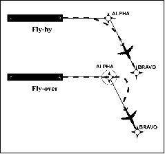
(1) Fly-by waypoints. Fly-by
waypoints are used when an aircraft should begin a turn to the next course prior
to reaching the waypoint separating the two route segments. This is known as
turn anticipation.
(2) Fly-over waypoints. Fly-over
waypoints are used when the aircraft must fly over the point prior to starting a
turn.
NOTE-
FIG 1-2-2 illustrates several differences between a
fly-by and a fly-over waypoint.
FIG 1-2-2
Fly-by and Fly-over Waypoints
(b) RNAV Leg Types. A
leg type describes the desired path proceeding, following, or between waypoints
on an RNAV procedure. Leg types are identified by a two-letter code that
describes the path (e.g., heading, course, track, etc.) and the termination
point (e.g., the path terminates at an altitude, distance, fix, etc.). Leg types
used for procedure design are included in the aircraft navigation database, but
not normally provided on the procedure chart. The narrative depiction of the
RNAV chart describes how a procedure is flown. The “path and terminator concept”
defines that every leg of a procedure has a termination point and some kind of
path into that termination point. Some of the available leg types are described
below.
(1) Track to Fix. A
Track to Fix (TF) leg is intercepted and acquired as the flight track to the
following waypoint. Track to a Fix legs are sometimes called point-to-point legs
for this reason. Narrative: “direct
ALPHA, then on course to BRAVO WP.” See
FIG 1-2-3.
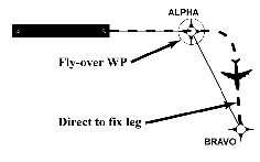
(2) Direct to Fix. A
Direct to Fix (DF) leg is a path described by an aircraft's track from an
initial area direct to the next waypoint. Narrative: “turn
right direct BRAVO WP.” See FIG 1-2-4.
FIG 1-2-3
Track to Fix Leg Type
FIG 1-2-4
Direct to Fix Leg Type
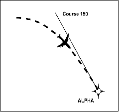
(3) Course to Fix. A
Course to Fix (CF) leg is a path that terminates at a fix with a specified
course at that fix. Narrative: “on
course 150 to ALPHA WP.” See FIG 1-2-5.
FIG 1-2-5
Course to Fix Leg Type
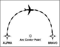
(4) Radius to Fix. A
Radius to Fix (RF) leg is defined as a constant radius circular path around a
defined turn center that terminates at a fix. See FIG
1-2-6.
FIG 1-2-6
Radius to Fix Leg Type
(5) Heading. A
Heading leg may be defined as, but not limited to, a Heading to Altitude (VA),
Heading to DME range (VD), and Heading to Manual Termination, i.e., Vector (VM).
Narrative: “climb
heading 350 to 1500”, “heading 265, at 9 DME west of PXR VORTAC, right turn
heading 360”, “fly heading 090, expect radar vectors to DRYHT INT.”
(c) Navigation Issues. Pilots
should be aware of their navigation system inputs, alerts, and annunciations in
order to make better-informed decisions. In addition, the availability and
suitability of particular sensors/systems should be considered.
(1) GPS/WAAS. Operators
using TSO-C129(), TSO-C196(), TSO-C145() or TSO-C146() systems should ensure
departure and arrival airports are entered to ensure proper RAIM availability
and CDI sensitivity.
(2) DME/DME. Operators
should be aware that DME/DME position updating is dependent on navigation system
logic and DME facility proximity, availability, geometry, and signal masking.
(3) VOR/DME. Unique
VOR characteristics may result in less accurate values from VOR/DME position
updating than from GPS or DME/DME position updating.
(4) Inertial Navigation. Inertial
reference units and inertial navigation systems are often coupled with other
types of navigation inputs, e.g., DME/DME or GPS, to improve overall navigation
system performance.
NOTE-
Specific inertial position updating requirements may apply.
(d) Flight Management
System (FMS). An FMS is an integrated suite of
sensors, receivers, and computers, coupled with a navigation database. These
systems generally provide performance and RNAV guidance to displays and
automatic flight control systems.
Inputs can be accepted from multiple sources
such as GPS, DME, VOR, LOC and IRU. These inputs may be applied to a navigation
solution one at a time or in combination. Some FMSs provide for the detection
and isolation of faulty navigation information.
When appropriate navigation signals are
available, FMSs will normally rely on GPS and/or DME/DME (that is, the use of
distance information from two or more DME stations) for position updates. Other
inputs may also be incorporated based on FMS system architecture and navigation
source geometry.
NOTE-
DME/DME inputs coupled with one or more IRU(s) are often abbreviated as
DME/DME/IRU or D/D/I.
(e) RNAV Navigation
Specifications (Nav Specs)
Nav Specs are a set of aircraft and aircrew
requirements needed to support a navigation application within a defined
airspace concept. For both RNP and RNAV designations, the numerical designation
refers to the lateral navigation accuracy in nautical miles which is expected to
be achieved at least 95 percent of the flight time by the population of aircraft
operating within the airspace, route, or procedure. (See FIG 1-2-1.)
(1) RNAV 1.
Typically RNAV 1 is used for DPs and STARs and appears on
the charts. Aircraft must maintain a total system error of not more than 1 NM
for 95 percent of the total flight time.
(2) RNAV 2.
Typically RNAV 2 is used for en route operations unless
otherwise specified. Troutes and Qroutes are examples of this Nav Spec.
Aircraft must maintain a total system error of not more than 2 NM for 95 percent
of the total flight time.
(3) RNAV 10.
Typically RNAV 10 is used in oceanic operations.
See paragraph 4-7-1
for specifics and explanation of the relationship between RNP 10 and RNAV 10
terminology.
1-2-2. Required Navigation
Performance (RNP)
a. General. RNP
is RNAV with onboard navigation monitoring and alerting. RNP is also a statement
of navigation performance necessary for operation within a defined airspace. A
critical component of RNP is the ability of the
aircraft navigation system to monitor its achieved navigation performance, and
to identify for the pilot whether the operational requirement is, or is not,
being met during an operation. This onboard
performance monitoring and alerting capability therefore allows a lessened
reliance on air traffic control intervention (via radar monitoring, automatic
dependent surveillance (ADS), multilateration, communications), and/or route
separation to achieve the overall safety of the operation. RNP capability of the
aircraft is a major component in determining the separation criteria to ensure
that the overall containment of the operation is met.
The RNP capability of an aircraft will vary
depending upon the aircraft equipment and the navigation infrastructure. For
example, an aircraft may be equipped and certified for RNP 1.0, but may not be
capable of RNP 1.0 operations due to limited NAVAID coverage.
b. RNP Operations.
1. Lateral Accuracy
Values. Lateral Accuracy values are applicable to a
selected airspace, route, or procedure. The lateral accuracy value is a value
typically expressed as a distance in nautical miles from the intended centerline
of a procedure, route, or path. RNP applications also account for potential
errors at some multiple of lateral accuracy value (for example, twice the RNP
lateral accuracy values).
(a) Nav Specs and
Standard Lateral Accuracy Values. U.S. standard
values supporting typical RNP airspace are as specified below. Other lateral
accuracy values as identified by ICAO, other states, and the FAA may also be
used. (See FIG 1-2-1.)
(1) RNP Approach
(APCH). RNP APCH
procedures are titled RNAV (GPS) and offer several lines of minima to
accommodate varying levels of aircraft equipage: either lateral navigation
(LNAV), LNAV/vertical navigation (LNAV/VNAV), and Localizer Performance with
Vertical Guidance (LPV), or LNAV, and Localizer Performance (LP). GPS or WAAS
can provide the lateral information to support LNAV minima. LNAV/VNAV
incorporates LNAV lateral with vertical path guidance for systems and operators
capable of either barometric or WAAS vertical. Pilots are required to use WAAS
to fly to the LPV or LP minima. RNP APCH has a lateral accuracy value of 1 in
the terminal and missed approach segments and essentially scales to RNP 0.3 in
the final approach. (See paragraph
1-1-19.)
(2) RNP AR APCH. RNP AR APCH procedures are titled
RNAV (RNP). RNP AR APCH vertical navigation performance is based upon barometric
VNAV or WAAS. RNP AR is intended to provide specific benefits at specific
locations. It is not intended for every operator or aircraft. RNP AR capability
requires specific aircraft performance, design, operational processes, training,
and specific procedure design criteria to achieve the required target level of
safety. RNP AR APCH has lateral accuracy values that can range below 1 in the
terminal and missed approach segments and essentially scale to RNP 0.3 or lower
in the final approach. Operators conducting these approaches should refer to AC
90101A, Approval Guidance for RNP Procedures with
AR. (See paragraph
5-4-18.)
(3) Advanced RNP
(ARNP). Advanced
RNP includes a lateral accuracy value of 2 for oceanic and remote operations but
not planned for U.S. implementation and may have a 2 or 1 lateral accuracy value
for domestic enroute segments. Except for the final approach, ARNP allows for
scalable RNP lateral navigation accuracies. Its applications in the U.S. are
still in progress.
(4) RNP 1.
RNP 1 requires a lateral accuracy value of 1 for
arrival and departure in the terminal area and the initial and intermediate
approach phase.
(5) RNP 2.
RNP 2 will apply to both domestic and
oceanic/remote operations with a lateral accuracy value of 2.
(6) RNP 4.
RNP 4 will apply to oceanic and remote operations only with
a lateral accuracy value of 4.
(7) RNP 0.3.
RNP 0.3 will apply to rotorcraft only. This Nav
Spec requires a lateral accuracy value of 0.3 for all phases of flight except
for oceanic and remote and the final approach segment.
(b) Application of
Standard Lateral Accuracy Values. U.S. standard
lateral accuracy values typically used for various routes and procedures
supporting RNAV operations may be based on use of a specific navigational system
or sensor such as GPS, or on multi-sensor RNAV systems having suitable
performance.
(c) Depiction of Lateral
Accuracy Values. The applicable lateral accuracy
values will be depicted on affected charts and procedures.
c. Other RNP
Applications Outside the U.S. The FAA and ICAO
member states have led initiatives in implementing the RNP concept to oceanic
operations. For example, RNP-10 routes have been established in the northern
Pacific (NOPAC) which has increased capacity and efficiency by reducing the
distance between tracks to 50 NM. (See paragraph
4-7-1.)
d. Aircraft and Airborne
Equipment Eligibility for RNP Operations. Aircraft
meeting RNP criteria will have an appropriate entry including special conditions
and limitations in its Aircraft Flight Manual (AFM), or supplement. Operators of
aircraft not having specific AFM-RNP certification may be issued operational
approval including special conditions and limitations for specific RNP lateral
accuracy values.
NOTE-
Some airborne systems use Estimated Position Uncertainty (EPU) as a measure of
the current estimated navigational performance. EPU may also be referred to as
Actual Navigation Performance (ANP) or Estimated Position Error (EPE).
TBL 1-2-1
U.S. Standard RNP Levels
|
RNP Level
|
Typical
Application
|
Primary Route Width (NM) -
Centerline to
Boundary
|
|
0.1 to 1.0
|
RNP AR Approach Segments
|
0.1 to 1.0
|
|
0.3 to 1.0
|
RNP Approach Segments
|
0.3 to 1.0
|
|
1
|
Terminal and En Route
|
1.0
|
|
2
|
En Route
|
2.0
|
|
4
|
Projected for oceanic/remote areas where 30 NM
horizontal separation is applied.
|
4.0
|
|
10
|
Oceanic/remote areas where 50 NM lateral separation
is applied.
|
10.0
|
1-2-3. Use of Suitable Area Navigation
(RNAV) Systems on Conventional
Procedures and Routes
a. Discussion. This paragraph sets forth policy,
while providing operational and airworthiness
guidance regarding the suitability and use of RNAV
systems when operating on, or transitioning to,
conventional, non-RNAV routes and procedures
within the U.S. National Airspace System (NAS):
1. Use of a suitable RNAV system as a
Substitute Means of Navigation when a Very-High
Frequency (VHF) Omni-directional Range (VOR),
Distance Measuring Equipment (DME), Tactical Air
Navigation (TACAN), VOR/TACAN (VORTAC),
VOR/DME, Non-directional Beacon (NDB), or
compass locator facility including locator outer
marker and locator middle marker is out-of-service
(that is, the navigation aid (NAVAID) information is
not available); an aircraft is not equipped with an
Automatic Direction Finder (ADF) or DME; or the
installed ADF or DME on an aircraft is not
operational. For example, if equipped with a suitable
RNAV system, a pilot may hold over an out-of-service NDB.
2. Use of a suitable RNAV system as an
Alternate Means of Navigation when a VOR, DME,
VORTAC, VOR/DME, TACAN, NDB, or compass
locator facility including locator outer marker and
locator middle marker is operational and the
respective aircraft is equipped with operational
navigation equipment that is compatible with
conventional navaids. For example, if equipped with
a suitable RNAV system, a pilot may fly a procedure
or route based on operational VOR using that RNAV
system without monitoring the VOR.
NOTE-
1. Additional information and associated requirements
are available in Advisory Circular 90108 titled “Use of
Suitable RNAV Systems on Conventional Routes and
Procedures.”
2. Good planning and knowledge of your RNAV system are
critical for safe and successful operations.
3. Pilots planning to use their RNAV system as a substitute
means of navigation guidance in lieu of an out-of-service
NAVAID may need to advise ATC of this intent and
capability.
4. The navigation database should be current for the
duration of the flight. If the AIRAC cycle will change
during flight, operators and pilots should establish
procedures to ensure the accuracy of navigation data,
including suitability of navigation facilities used to define
the routes and procedures for flight. To facilitate validating
database currency, the FAA has developed procedures for
publishing the amendment date that instrument approach
procedures were last revised. The amendment date follows
the amendment number, e.g., Amdt 4 14Jan10. Currency of
graphic departure procedures and STARs may be
ascertained by the numerical designation in the procedure
title. If an amended chart is published for the procedure, or
the procedure amendment date shown on the chart is on or
after the expiration date of the database, the operator must
not use the database to conduct the operation.
b. Types of RNAV Systems that Qualify as a
Suitable RNAV System. When installed in accordance with appropriate airworthiness installation
requirements and operated in accordance with
applicable operational guidance (e.g., aircraft flight
manual and Advisory Circular material), the
following systems qualify as a suitable RNAV
system:
1. An RNAV system with TSO-C129/
-C145/-C146 equipment, installed in accordance
with AC 20-138, Airworthiness Approval of Global
Positioning System (GPS) Navigation Equipment for
Use as a VFR and IFR Supplemental Navigation
System, or AC 20-130A, Airworthiness Approval of
Navigation or Flight Management Systems Integrating Multiple Navigation Sensors, and authorized for
instrument flight rules (IFR) en route and terminal
operations (including those systems previously
qualified for “GPS in lieu of ADF or DME”
operations), or
2. An RNAV system with DME/DME/IRU
inputs that is compliant with the equipment
provisions of AC 90-100A, U.S. Terminal and
En Route Area Navigation (RNAV) Operations, for
RNAV routes. A table of compliant equipment is
available at the following website:
http://www.faa.gov/about/office_org/headquarters_offices/avs/offices/afs/
afs400/afs470/policy_guidance/
NOTE-
Approved RNAV systems using DME/DME/IRU, without
GPS/WAAS position input, may only be used as a substitute
means of navigation when specifically authorized by a
Notice to Airmen (NOTAM) or other FAA guidance for a
specific procedure. The NOTAM or other FAA guidance
authorizing the use of DME/DME/IRU systems will also
identify any required DME facilities based on an FAA
assessment of the DME navigation infrastructure.
c. Uses of Suitable RNAV Systems. Subject to
the operating requirements, operators may use a
suitable RNAV system in the following ways.
1. Determine aircraft position relative to, or
distance from a VOR (see NOTE 5 below), TACAN,
NDB, compass locator, DME fix; or a named fix
defined by a VOR radial, TACAN course, NDB
bearing, or compass locator bearing intersecting a
VOR or localizer course.
2. Navigate to or from a VOR, TACAN, NDB,
or compass locator.
3. Hold over a VOR, TACAN, NDB, compass
locator, or DME fix.
4. Fly an arc based upon DME.
NOTE-
1. The allowances described in this section apply even
when a facility is identified as required on a procedure (for
example, “Note ADF required”).
2. These operations do not include lateral navigation on
localizer-based courses (including localizer back-course
guidance) without reference to raw localizer data.
3. Unless otherwise specified, a suitable RNAV system
cannot be used for navigation on procedures that are
identified as not authorized (“NA”) without exception by
a NOTAM. For example, an operator may not use a RNAV
system to navigate on a procedure affected by an expired or
unsatisfactory flight inspection, or a procedure that is
based upon a recently decommissioned NAVAID.
4. Pilots may not substitute for the NAVAID (for example,
a VOR or NDB) providing lateral guidance for the final
approach segment. This restriction does not refer to
instrument approach procedures with “or GPS” in the title
when using GPS or WAAS. These allowances do not apply
to procedures that are identified as not authorized (NA)
without exception by a NOTAM, as other conditions may
still exist and result in a procedure not being available. For
example, these allowances do not apply to a procedure
associated with an expired or unsatisfactory flight
inspection, or is based upon a recently decommissioned
NAVAID.
5. For the purpose of paragraph c, “VOR” includes VOR,
VOR/DME, and VORTAC facilities and “compass
locator” includes locator outer marker and locator middle
marker.
d. Alternate Airport Considerations.
For the purposes of flight planning, any required alternate airport must have an
available instrument approach procedure that does not require the use of GPS.
This restriction includes conducting a conventional approach at the alternate
airport using a substitute means of navigation that is based upon the use of
GPS. For example, these restrictions would apply when planning to use GPS
equipment as a substitute means of navigation for an out-of-service VOR that
supports an ILS missed approach procedure at an alternate airport. In this case,
some other approach not reliant upon the use of GPS must be available. This
restriction does not apply to RNAV systems using TSO-C145/-C146 WAAS equipment.
For further WAAS guidance see paragraph 1-1-19.
1. For
flight planning purposes, TSOC129() and TSOC196() equipped users (GPS users)
whose navigation systems have fault detection and exclusion (FDE) capability,
who perform a preflight RAIM prediction at the airport where the RNAV (GPS)
approach will be flown, and have proper knowledge and any required training
and/or approval to conduct a GPSbased IAP, may file based on a GPSbased IAP at
either the destination or the alternate airport, but not at both locations. At
the alternate airport, pilots may plan for applicable alternate airport weather
minimums using:
(a) Lateral
navigation (LNAV) or circling minimum descent altitude (MDA);
(b) LNAV/vertical
navigation (LNAV/VNAV) DA, if equipped with and using approved barometric
vertical navigation (baroVNAV) equipment;
(c) RNP
0.3 DA on an RNAV (RNP) IAP, if they are specifically authorized users using
approved baroVNAV equipment and the pilot has verified required navigation
performance (RNP) availability through an approved prediction program.
2. If
the above conditions cannot be met, any required alternate airport must have an
approved instrument approach procedure other than GPS that is anticipated to be
operational and available at the estimated time of arrival, and which the
aircraft is equipped to fly.
3. This
restriction does not apply to TSOC145() and TSOC146() equipped users (WAAS
users). For further WAAS guidance see paragraph
1-1-19.
|