Section 3. En Route Procedures5-3-1. ARTCC Communications a. Direct Communications, Controllers and Pilots. 1. ARTCCs are capable of direct communications with IFR air traffic on certain frequencies. Maximum communications coverage is possible through the use of Remote Center Air/Ground (RCAG) sites comprised of both VHF and UHF transmitters and receivers. These sites are located throughout the U.S. Although they may be several hundred miles away from the ARTCC, they are remoted to the various ARTCCs by land lines or microwave links. Since IFR operations are expedited through the use of direct communications, pilots are requested to use these frequencies strictly for communications pertinent to the control of IFR aircraft. Flight plan filing, en route weather, weather forecasts, and similar data should be requested through FSSs, company radio, or appropriate military facilities capable of performing these services. 2. An ARTCC is divided into sectors. Each sector is handled by one or a team of controllers and has its own sector discrete frequency. As a flight progresses from one sector to another, the pilot is requested to change to the appropriate sector discrete frequency. 3. Controller Pilot Data Link Communications (CPDLC) is a system that supplements air/ground voice communications. As a result, it expands two-way air traffic control air/ground communications capabilities. Consequently, the air traffic system's operational capacity is increased and any associated air traffic delays become minimized. A related safety benefit is that pilot/controller read-back and hear-back errors will be significantly reduced. The CPDLC's principal operating criteria are: (a) Voice remains the primary and controlling air/ground communications means. (b) Participating aircraft will need to have the appropriate CPDLC avionics equipment in order to receive uplink or transmit downlink messages. (c) CPDLC Build 1 offers four ATC data link services. These are altimeter setting (AS), transfer of communications (TC), initial contact (IC), and menu text messages (MT). (1) Altimeter settings are usually transmitted automatically when a CPDLC session and eligibility has been established with an aircraft. A controller may also manually send an altimeter setting message. NOTE- (2) Initial contact is a safety validation transaction that compares a pilot's initiated altitude downlink message with an aircraft's ATC host computer stored altitude. If an altitude mismatch is detected, the controller will verbally provide corrective action. (3) Transfer of communications automatically establishes data link contact with a succeeding sector. (4) Menu text transmissions are scripted nontrajectory altering uplink messages. NOTE- b. ATC Frequency Change Procedures. 1. The following phraseology will be used by controllers to effect a frequency change: EXAMPLE- NOTE- 2. The following phraseology should be utilized by pilots for establishing contact with the designated facility: (a) When operating in a radar environment: On initial contact, the pilot should inform the controller of the aircraft's assigned altitude preceded by the words “level,” or “climbing to,” or “descending to,” as appropriate; and the aircraft's present vacating altitude, if applicable. EXAMPLE- 2. (Name) CENTER, (aircraft identification), LEAVING (exact altitude or flight level), CLIMBING TO OR DESCENDING TO (altitude of flight level). NOTE- (b) When operating in a nonradar environment: (1) On initial contact, the pilot should inform the controller of the aircraft's present position, altitude and time estimate for the next reporting point. EXAMPLE- (2) After initial contact, when a position report will be made, the pilot should give the controller a complete position report. EXAMPLE- REFERENCE- 3. At times controllers will ask pilots to verify that they are at a particular altitude. The phraseology used will be: “VERIFY AT (altitude).” In climbing or descending situations, controllers may ask pilots to “VERIFY ASSIGNED ALTITUDE AS (altitude).” Pilots should confirm that they are at the altitude stated by the controller or that the assigned altitude is correct as stated. If this is not the case, they should inform the controller of the actual altitude being maintained or the different assigned altitude. CAUTION- c. ARTCC Radio Frequency Outage. ARTCCs normally have at least one back‐up radio receiver and transmitter system for each frequency, which can usually be placed into service quickly with little or no disruption of ATC service. Occasionally, technical problems may cause a delay but switchover seldom takes more than 60 seconds. When it appears that the outage will not be quickly remedied, the ARTCC will usually request a nearby aircraft, if there is one, to switch to the affected frequency to broadcast communications instructions. It is important, therefore, that the pilot wait at least 1 minute before deciding that the ARTCC has actually experienced a radio frequency failure. When such an outage does occur, the pilot should, if workload and equipment capability permit, maintain a listening watch on the affected frequency while attempting to comply with the following recommended communications procedures: 1. If two-way communications cannot be established with the ARTCC after changing frequencies, a pilot should attempt to recontact the transferring controller for the assignment of an alternative frequency or other instructions. 2. When an ARTCC radio frequency failure occurs after two‐way communications have been established, the pilot should attempt to reestablish contact with the center on any other known ARTCC frequency, preferably that of the next responsible sector when practicable, and ask for instructions. However, when the next normal frequency change along the route is known to involve another ATC facility, the pilot should contact that facility, if feasible, for instructions. If communications cannot be reestablished by either method, the pilot is expected to request communications instructions from the FSS appropriate to the route of flight. NOTE- 5-3-2. Position Reporting The safety and effectiveness of traffic control depends to a large extent on accurate position reporting. In order to provide the proper separation and expedite aircraft movements, ATC must be able to make accurate estimates of the progress of every aircraft operating on an IFR flight plan. a. Position Identification. 1. When a position report is to be made passing a VOR radio facility, the time reported should be the time at which the first complete reversal of the “to/from” indicator is accomplished. 2. When a position report is made passing a facility by means of an airborne ADF, the time reported should be the time at which the indicator makes a complete reversal. 3. When an aural or a light panel indication is used to determine the time passing a reporting point, such as a fan marker, Z marker, cone of silence or intersection of range courses, the time should be noted when the signal is first received and again when it ceases. The mean of these two times should then be taken as the actual time over the fix. 4. If a position is given with respect to distance and direction from a reporting point, the distance and direction should be computed as accurately as possible. 5. Except for terminal area transition purposes, position reports or navigation with reference to aids not established for use in the structure in which flight is being conducted will not normally be required by ATC. b. Position Reporting Points. CFRs require
pilots to maintain a listening watch on the appropriate
frequency and, unless operating under the provisions
of subparagraph c, to furnish position reports passing
certain reporting points. Reporting points are
indicated by symbols on en route charts. The
designated compulsory reporting point symbol is a
solid triangle
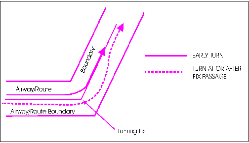
c. Position Reporting Requirements. 1. Flights Along Airways or Routes. A position report is required by all flights regardless of altitude, including those operating in accordance with an ATC clearance specifying “VFR-on-top,” over each designated compulsory reporting point along the route being flown. 2. Flights Along a Direct Route. Regardless of the altitude or flight level being flown, including flights operating in accordance with an ATC clearance specifying “VFR-on-top,” pilots must report over each reporting point used in the flight plan to define the route of flight. 3. Flights in a Radar Environment. When informed by ATC that their aircraft are in “Radar Contact,” pilots should discontinue position reports over designated reporting points. They should resume normal position reporting when ATC advises “RADAR CONTACT LOST” or “RADAR SERVICE TERMINATED.” 4. Flights in an Oceanic (Nonradar) Environment. Pilots must report over each point used in the flight plan to define the route of flight, even if the point is depicted on aeronautical charts as an “on request" (noncompulsory) reporting point. For aircraft providing automatic position reporting via an Automatic Dependent SurveillanceContract (ADSC) logon, pilots should discontinue voice position reports. NOTE- d. Position Report Items: 1. Position reports should include the following items: (a) Identification; (b) Position; (c) Time; (d) Altitude or flight level (include actual altitude or flight level when operating on a clearance specifying VFR-on-top); (e) Type of flight plan (not required in IFR position reports made directly to ARTCCs or approach control); (f) ETA and name of next reporting point; (g) The name only of the next succeeding reporting point along the route of flight; and (h) Pertinent remarks. 5-3-3. Additional Reports a. The following reports should be made to ATC or FSS facilities without a specific ATC request: 1. At all times. (a) When vacating any previously assigned altitude or flight level for a newly assigned altitude or flight level. (b) When an altitude change will be made if operating on a clearance specifying VFR-on-top. (c) When unable to climb/descend at a rate of a least 500 feet per minute. (d) When approach has been missed. (Request clearance for specific action; i.e., to alternative airport, another approach, etc.) (e) Change in the average true airspeed (at cruising altitude) when it varies by 5 percent or 10 knots (whichever is greater) from that filed in the flight plan. (f) The time and altitude or flight level upon reaching a holding fix or point to which cleared. (g) When leaving any assigned holding fix or point. NOTE- (h) Any loss, in controlled airspace, of VOR, TACAN, ADF, low frequency navigation receiver capability, GPS anomalies while using installed IFR-certified GPS/GNSS receivers, complete or partial loss of ILS receiver capability or impairment of air/ground communications capability. Reports should include aircraft identification, equipment affected, degree to which the capability to operate under IFR in the ATC system is impaired, and the nature and extent of assistance desired from ATC. NOTE- 2. When reporting GPS anomalies, include the location and altitude of the anomaly. Be specific when describing the location and include duration of the anomaly if necessary. (i) Any information relating to the safety of flight. 2. When not in radar contact. (a) When leaving final approach fix inbound on final approach (nonprecision approach) or when leaving the outer marker or fix used in lieu of the outer marker inbound on final approach (precision approach). (b) A corrected estimate at anytime it becomes apparent that an estimate as previously submitted is in error in excess of 2 minutes. For flights in the North Atlantic (NAT), a revised estimate is required if the error is 3 minutes or more. b. Pilots encountering weather conditions which have not been forecast, or hazardous conditions which have been forecast, are expected to forward a report of such weather to ATC. REFERENCE- 5-3-4. Airways and Route Systems a. Three fixed route systems are established for air navigation purposes. They are the Federal airway system (consisting of VOR and L/MF routes), the jet route system, and the RNAV route system. To the extent possible, these route systems are aligned in an overlying manner to facilitate transition between each. 1. The VOR and L/MF (nondirectional radio beacons) Airway System consists of airways designated from 1,200 feet above the surface (or in some instances higher) up to but not including 18,000 feet MSL. These airways are depicted on IFR Enroute Low Altitude Charts. NOTE- (a) Except in Alaska, the VOR airways are: predicated solely on VOR or VORTAC navigation aids; depicted in black on aeronautical charts; and identified by a “V” (Victor) followed by the airway number (for example, V12). NOTE- (1) A segment of an airway which is common to two or more routes carries the numbers of all the airways which coincide for that segment. When such is the case, pilots filing a flight plan need to indicate only that airway number for the route filed. NOTE- (2) With respect to position reporting, reporting points are designated for VOR Airway Systems. Flights using Victor Airways will report over these points unless advised otherwise by ATC. (b) The L/MF airways (colored airways) are predicated solely on L/MF navigation aids and are depicted in brown on aeronautical charts and are identified by color name and number (e.g., Amber One). Green and Red airways are plotted east and west. Amber and Blue airways are plotted north and south. NOTE- (c) The use of TSO-C145 (as revised) or TSO-C146 (as revised) GPS/WAAS navigation systems is allowed in Alaska as the only means of navigation on published air traffic service (ATS) routes, including those Victor, T-Routes, and colored airway segments designated with a second minimum en route altitude (MEA) depicted in blue and followed by the letter G at those lower altitudes. The altitudes so depicted are below the minimum reception altitude (MRA) of the land-based navigation facility defining the route segment, and guarantee standard en route obstacle clearance and two-way communications. Air carrier operators requiring operations specifications are authorized to conduct operations on those routes in accordance with FAA operations specifications. 2. The jet route system consists of jet routes established from 18,000 feet MSL to FL 450 inclusive. (a) These routes are depicted on Enroute High Altitude Charts. Jet routes are depicted in black on aeronautical charts and are identified by a “J” (Jet) followed by the airway number (e.g., J12). Jet routes, as VOR airways, are predicated solely on VOR or VORTAC navigation facilities (except in Alaska). NOTE- (b) With respect to position reporting, reporting points are designated for jet route systems. Flights using jet routes will report over these points unless otherwise advised by ATC. 3. Area Navigation (RNAV) Routes. (a) Published RNAV routes, including Q-Routes and T-Routes, can be flight planned for use by aircraft with RNAV capability, subject to any limitations or requirements noted on en route charts, in applicable Advisory Circulars, or by NOTAM. RNAV routes are depicted in blue on aeronautical charts and are identified by the letter “Q” or “T” followed by the airway number (for example, Q-13, T-205). Published RNAV routes are RNAV-2 except when specifically charted as RNAV-1. These routes require system performance currently met by GPS, GPS/WAAS, or DME/DME/IRU RNAV systems that satisfy the criteria discussed in AC 90-100A, U.S. Terminal and En Route Area Navigation (RNAV) Operations. NOTE- (1) Q-routes are available for use by RNAV equipped aircraft between 18,000 feet MSL and FL 450 inclusive. Q-routes are depicted on Enroute High Altitude Charts. NOTE- (2) T-routes are available for use by GPS or GPS/WAAS equipped aircraft from 1,200 feet above the surface (or in some instances higher) up to but not including 18,000 feet MSL. T-routes are depicted on Enroute Low Altitude Charts. NOTE- (b) Unpublished RNAV routes are direct routes, based on area navigation capability, between waypoints defined in terms of latitude/longitude coordinates, degree-distance fixes, or offsets from established routes/airways at a specified distance and direction. Radar monitoring by ATC is required on all unpublished RNAV routes, except for GNSS-equipped aircraft cleared via filed published waypoints recallable from the aircraft's navigation database. (c) Magnetic Reference Bearing (MRB) is the published bearing between two waypoints on an RNAV/GPS/GNSS route. The MRB is calculated by applying magnetic variation at the waypoint to the calculated true course between two waypoints. The MRB enhances situational awareness by indicating a reference bearing (no-wind heading) that a pilot should see on the compass/HSI/RMI, etc., when turning prior to/over a waypoint en route to another waypoint. Pilots should use this bearing as a reference only, because their RNAV/GPS/GNSS navigation system will fly the true course between the waypoints. b. Operation above FL 450 may be conducted on a point‐to‐point basis. Navigational guidance is provided on an area basis utilizing those facilities depicted on the enroute high altitude charts. c. Radar Vectors. Controllers may vector aircraft within controlled airspace for separation purposes, noise abatement considerations, when an operational advantage will be realized by the pilot or the controller, or when requested by the pilot. Vectors outside of controlled airspace will be provided only on pilot request. Pilots will be advised as to what the vector is to achieve when the vector is controller initiated and will take the aircraft off a previously assigned nonradar route. To the extent possible, aircraft operating on RNAV routes will be allowed to remain on their own navigation. d. When flying in Canadian airspace, pilots are cautioned to review Canadian Air Regulations. 1. Special attention should be given to the parts which differ from U.S. CFRs. (a) The Canadian Airways Class B airspace restriction is an example. Class B airspace is all controlled low level airspace above 12,500 feet MSL or the MEA, whichever is higher, within which only IFR and controlled VFR flights are permitted. (Low level airspace means an airspace designated and defined as such in the Designated Airspace Handbook.) (b) Unless issued a VFR flight clearance by ATC, regardless of the weather conditions or the height of the terrain, no person may operate an aircraft under VMC within Class B airspace. (c) The requirement for entry into Class B airspace is a student pilot permit (under the guidance or control of a flight instructor). (d) VFR flight requires visual contact with the ground or water at all times. 2. Segments of VOR airways and high level routes in Canada are based on L/MF navigation aids and are charted in brown color instead of blue on en route charts. FIG 5-3-1
|
|
Altitude (MSL) |
Airspeed (KIAS) |
|
MHA - 6,000' |
200 |
|
6,001' - 14,000' |
230 |
|
14,001' and above |
265 |
(b) The following are exceptions to the maximum holding airspeeds:
(1) Holding patterns from 6,001' to 14,000' may be restricted to a maximum airspeed of 210 KIAS. This nonstandard pattern will be depicted by an icon.
(2) Holding patterns may be restricted to a maximum speed. The speed restriction is depicted in parenthesis inside the holding pattern on the chart: e.g., (175). The aircraft should be at or below the maximum speed prior to initially crossing the holding fix to avoid exiting the protected airspace. Pilots unable to comply with the maximum airspeed restriction should notify ATC.
(3) Holding patterns at USAF airfields only - 310 KIAS maximum, unless otherwise depicted.
(4) Holding patterns at Navy fields only - 230 KIAS maximum, unless otherwise depicted.
(5) When a climb-in hold is specified by a published procedure (e.g., “Climb-in holding pattern to depart XYZ VORTAC at or above 10,000.” or “All aircraft climb-in TRUCK holding pattern to cross TRUCK Int at or above 11,500 before proceeding on course.”), additional obstacle protection area has been provided to allow for greater airspeeds in the climb for those aircraft requiring them. The holding pattern template for a maximum airspeed of 310 KIAS has been used for the holding pattern if there are no airspeed restrictions on the holding pattern as specified in subparagraph j2(b)(2) of this paragraph. Where the holding pattern is restricted to a maximum airspeed of 175 KIAS, the 200 KIAS holding pattern template has been applied for published climb-in hold procedures for altitudes 6,000 feet and below and the 230 KIAS holding pattern template has been applied for altitudes above 6,000 feet. The airspeed limitations in 14 CFR Section 91.117, Aircraft Speed, still apply.
(c) The following phraseology may be used by an ATCS to advise a pilot of the maximum holding airspeed for a holding pattern airspace area.
PHRASEOLOGY-
(AIRCRAFT IDENTIFICATION) (holding instructions,
when needed) MAXIMUM HOLDING AIRSPEED IS
(speed in knots).
FIG 5-3-4
Holding Pattern Entry Procedures
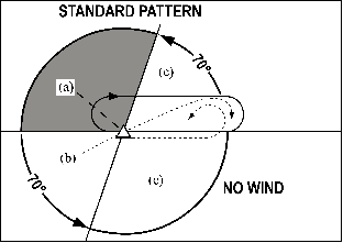
3. Entry Procedures. (See FIG 5-3-4.)
(a) Parallel Procedure. When approaching the holding fix from anywhere in sector (a), the parallel entry procedure would be to turn to a heading to parallel the holding course outbound on the nonholding side for one minute, turn in the direction of the holding pattern through more than 180 degrees, and return to the holding fix or intercept the holding course inbound.
(b) Teardrop Procedure. When approaching the holding fix from anywhere in sector (b), the teardrop entry procedure would be to fly to the fix, turn outbound to a heading for a 30 degree teardrop entry within the pattern (on the holding side) for a period of one minute, then turn in the direction of the holding pattern to intercept the inbound holding course.
(c) Direct Entry Procedure. When approaching the holding fix from anywhere in sector (c), the direct entry procedure would be to fly directly to the fix and turn to follow the holding pattern.
(d) While other entry procedures may enable the aircraft to enter the holding pattern and remain within protected airspace, the parallel, teardrop and direct entries are the procedures for entry and holding recommended by the FAA.
4. Timing.
(a) Inbound Leg.
(1) At or below 14,000 feet MSL: 1 minute.
(2) Above 14,000 feet MSL: 11/2 minutes.
NOTE-
The initial outbound leg should be flown for 1 minute or
1 1/2 minutes (appropriate to altitude). Timing for
subsequent outbound legs should be adjusted, as
necessary, to achieve proper inbound leg time. Pilots may
use any navigational means available; i.e., DME, RNAV,
etc., to ensure the appropriate inbound leg times.
(b) Outbound leg timing begins over/abeam the fix, whichever occurs later. If the abeam position cannot be determined, start timing when turn to outbound is completed.
5. Distance Measuring Equipment (DME)/ GPS Along-Track Distance (ATD). DME/GPS holding is subject to the same entry and holding procedures except that distances (nautical miles) are used in lieu of time values. The outbound course of the DME/GPS holding pattern is called the outbound leg of the pattern. The controller or the instrument approach procedure chart will specify the length of the outbound leg. The end of the outbound leg is determined by the DME or ATD readout. The holding fix on conventional procedures, or controller defined holding based on a conventional navigation aid with DME, is a specified course or radial and distances are from the DME station for both the inbound and outbound ends of the holding pattern. When flying published GPS overlay or stand alone procedures with distance specified, the holding fix will be a waypoint in the database and the end of the outbound leg will be determined by the ATD. Some GPS overlay and early stand alone procedures may have timing specified. (See FIG 5-3-5, FIG 5-3-6 and FIG 5-3-7.) See paragraph 1-1-19, Global Positioning System (GPS), for requirements and restriction on using GPS for IFR operations.
FIG 5-3-5
Inbound Toward NAVAID
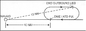
NOTE-
When the inbound course is toward the NAVAID, the fix distance is 10 NM, and the leg length is 5 NM, then the end of the
outbound leg will be reached when the DME/ATD reads 15 NM.
FIG 5-3-6
Inbound Leg Away from NAVAID
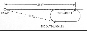
NOTE-
When the inbound course is away from the NAVAID and the fix distance is 28 NM, and the leg length is 8 NM, then the end
of the outbound leg will be reached when the DME/ATD reads 20 NM.
FIG 5-3-7
GPS/RNAV Holding
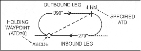
NOTE-
The inbound course is always toward the waypoint and the ATD is zero at the waypoint. The end of the outbound leg of the
holding pattern is reached when the ATD reads the specified distance.
6. Pilot Action.
(a) Start speed reduction when 3 minutes or less from the holding fix. Cross the holding fix, initially, at or below the maximum holding airspeed.
(b) Make all turns during entry and while holding at:
(1) 3 degrees per second; or
(2) 30 degree bank angle; or
(3) 25 degree bank provided a flight director system is used.
NOTE-
Use whichever requires the least bank angle.
(c) Compensate for wind effect primarily by drift correction on the inbound and outbound legs. When outbound, triple the inbound drift correction to avoid major turning adjustments; e.g., if correcting left by 8 degrees when inbound, correct right by 24 degrees when outbound.
(d) Determine entry turn from aircraft heading upon arrival at the holding fix; +/-5 degrees in heading is considered to be within allowable good operating limits for determining entry.
(e) Advise ATC immediately what increased airspeed is necessary, if any, due to turbulence, icing, etc., or if unable to accomplish any part of the holding procedures. When such higher speeds become no longer necessary, operate according to the appropriate published holding speed and notify ATC.
7. Nonstandard Holding Pattern. Fix end and outbound end turns are made to the left. Entry procedures to a nonstandard pattern are oriented in relation to the 70 degree line on the holding side just as in the standard pattern.
k. When holding at a fix and instructions are received specifying the time of departure from the fix, the pilot should adjust the aircraft's flight path within the limits of the established holding pattern in order to leave the fix at the exact time specified. After departing the holding fix, normal speed is to be resumed with respect to other governing speed requirements, such as terminal area speed limits, specific ATC requests, etc. Where the fix is associated with an instrument approach and timed approaches are in effect, a procedure turn must not be executed unless the pilot advises ATC, since aircraft holding are expected to proceed inbound on final approach directly from the holding pattern when approach clearance is received.
l. Radar surveillance of outer fix holding pattern airspace areas.
1. Whenever aircraft are holding at an outer fix, ATC will usually provide radar surveillance of the outer fix holding pattern airspace area, or any portion of it, if it is shown on the controller's radar scope.
2. The controller will attempt to detect any holding aircraft that stray outside the holding pattern airspace area and will assist any detected aircraft to return to the assigned airspace area.
NOTE-
Many factors could prevent ATC from providing this
additional service, such as workload, number of targets,
precipitation, ground clutter, and radar system capability.
These circumstances may make it unfeasible to maintain
radar identification of aircraft to detect aircraft straying
from the holding pattern. The provision of this service
depends entirely upon whether controllers believe they are
in a position to provide it and does not relieve a pilot of their
responsibility to adhere to an accepted ATC clearance.
3. If an aircraft is established in a published holding pattern at an assigned altitude above the published minimum holding altitude and subsequently cleared for the approach, the pilot may descend to the published minimum holding altitude. The holding pattern would only be a segment of the IAP if it is published on the instrument procedure chart and is used in lieu of a procedure turn.
m. For those holding patterns where there are no published minimum holding altitudes, the pilot, upon receiving an approach clearance, must maintain the last assigned altitude until leaving the holding pattern and established on the inbound course. Thereafter, the published minimum altitude of the route segment being flown will apply. It is expected that the pilot will be assigned a holding altitude that will permit a normal descent on the inbound course.