Section 8. Other Displays
3-8-1. MINIMUM
VECTORING ALTITUDE CHARTS (MVAC) FOR FACILITIES PROVIDING TERMINAL
APPROACH CONTROL SERVICES
Air traffic
managers must determine the location and the method for the display of
vectoring altitude charts to provide controllers with the minimum
vectoring altitudes as follows:
a. Where the
system is configured to display single radar sensors, provide:
1. An MVAC
that accommodates the largest separation minima of all available sensors;
or
2. Unique
MVACs that accommodate the appropriate separation minima of each available
sensor.
b. Where the system is configured to simultaneously display multiple radar sensors, provide an
MVAC that accommodates the largest separation
minima of all available sensors; or
c. Where the system is utilizing FUSION mode,
develop an MVAC that provides:
1. Threemile separation minima or more from
obstacles, except when applying the provision in
paragraph 381c2. The MVAC must depict obstacle
clearances, outward to the lateral limits of the
associated approach control airspace and an
appropriate buffer outside the lateral approach
control airspace boundaries. As a minimum, this may
be accomplished by using the existing singlesensor
MVAC for the predominant radar sensor; and
2. Five-mile separation minima from obstacles
for use whenever the FUSION system cannot provide
3-mile separation due to degraded status or system
limitations.
d. At locations adding FUSION, provided the
facility uses existing MVA charts with 3-mile buffers
and an MVAC with 5-mile buffers, additional charts
do not need to be developed to support FUSION.
NOTE-
Mission Support Services-Aeronautical Products, ATC
Products Group should be contacted if assistance is
required. (See FAAO 8260.3, United States Standard for
Terminal Instrument Procedures (TERPS) Chapter 10.)
REFERENCE-
FAAO JO 7110.65, Para 5-5-4, Minima.
3-8-2. MINIMUM
VECTORING ALTITUDE CHARTS (MVAC) PREPARATION (TERMINAL/MEARTS)
Prepare a vectoring
chart in accordance with the criteria contained in FAA Order 8260.3,
United States Standard for Terminal Instrument Procedures (TERPS).
a. MVACs must be developed
and maintained using the Sector Design and Analysis Tool (SDAT). Facility
Managers may request assistance in the development and maintenance of
their MVAC or request SDAT user support by soliciting the Mission Support
Services, Geographic Services Group. MVACs developed in SDAT properly
apply obstruction clearance criteria required by FAA Order 8260.3. SDAT
completes FAA Form 7210-9 and automatically creates and sends the
necessary data files to Mission Support Services, ATC Products Group upon
certification for subsequent
radar video map creation. Facility correspondence to ATC Products
regarding MVACs and video maps must be accomplished via email to
9-AJV-HQ-ATCPRODUCTS.
NOTE-
MVAs are established without considering the flight-checked radar coverage
in the sector concerned. They are based on obstruction clearance criteria
and controlled airspace only. It is the responsibility of the controller
to determine that a target return is adequate for radar control purposes.
b. At a
minimum, the airspace considered for providing obstacle clearance
information on MVA charts must accommodate the facility's delegated area
of control as well as adjacent airspace where control responsibility is
assumed because of early handoff or track initiation.
c. MVACs may
be subdivided into sectors to gain relief from obstacles that are clear of
the area in which flight is to be conducted. There is no prescribed limit
on the size, shape, or orientation of the sectors.
d. Depict
the sectors in relationship to true north from the antenna site.
e. Facility
requests for reduced required obstruction clearance (ROC) in an area
designated as mountainous in accordance with 14 CFR, Part 95, Subpart B,
must conform to the following procedures:
1. Designated
mountainous terrain must be evaluated for precipitous terrain
characteristics and the associated negative effects. Facility managers
must use FAA Order 8260.3, paragraph 1720, as a guide when considering ROC
reductions in designated mountainous areas. ROC reductions are not
authorized where negative effects of precipitous terrain are documented or
known having followed the process contained in subparas e2 and 3 below.
ROC reductions within designated mountainous areas are only authorized by
complying with at least one of the following criteria:
REFERENCE-
FAA Order 8260.3, Appendix 1, Glossary Term, Precipitous Terrain.
(a) Where lower altitudes are required to achieve compatibility
with terminal routes.
(b) To
permit vectoring within the airport radar traffic pattern area for either
a departure procedure, an instrument approach procedure, or a visual
approach to an airport. Air traffic managers must define each airport's
radar traffic pattern area for which ROC reductions are sought. These
areas must include sufficient maneuvering airspace necessary for ATC
sequencing and spacing of traffic in the vicinity of an airport.
2. Where
mountainous terrain has been deemed precipitous by the air traffic
facility, each ROC reduction request must include a query to an
independent data source, such as NASA's Aviation Safety Reporting System
to determine if any ground proximity warnings have been reported in the
subject area. After completing the query, consider the facility's history
and experiences with turbulence at the minimum altitude requested. Avoid
ROC reductions where reported ground proximity warnings relate to both
existing MVA sector altitude ROC reductions and rapid terrain elevation
changes. ROC reduction requests in these areas may require additional
evaluation and review.
REFERENCE-
FAA Order 8260.3, Appendix 1, Glossary Term, Precipitous Terrain.
3. The
facility MVAC package must include a detailed account of the steps taken
by the facility to determine if the sector will qualify for taking a ROC
reduction in the sector. This data will be reviewed by the Service Center
Operations Support Group (OSG) and the ATC Products Group personnel for
ROC reduction approval. Service Center Operations Support personnel must
be the approving authority for ROC reduction criteria compliance with
paragraph e1(a) and (b) above. Previously approved reductions in ROC
justifications must be resubmitted for approval during a facility's
recurring certification process.
NOTE-
Should a ROC reduction request be denied by Service Center Operations
Support personnel, the manager may appeal the decision to Terminal Safety
and Operations Support for review.
4. In the
advent of the development of an automated precipitous terrain algorithm
certified by AFS, the automated method will be used in lieu of the manual
method described above.
5. Ensure
MVA areas submitted for ROC reductions do not cover large geographical
areas that include locations that would not, individually, meet ROC
reduction standards. In such cases, the ATC Products Group may work with
the Service Center and the facility to design a sector that will pass the
approval process for a particular approach/departure route.
6. Whenever
a ROC reduction is taken, the rationale/justification for taking the ROC
reduction as defined in subpara e1 must be included in the MVAC package by
facility managers.
7. ROC
reductions should only be requested when there is a demonstrated
operational need.
f. An
assumed adverse obstacle (AAO) additive is required in areas not
designated as mountainous (ROC 1,000 feet) and in designated mountainous
terrain areas when any ROC reduction is requested.
g. Resultant
MVAs may be rounded down to the nearest 100-foot increment (those that
are xx49 feet or less), except in the following cases:
1. Any
locations outside of the Contiguous United States.
2. Where any part of an MVA Sector is more than
65 NM from the issued altimeter source.
3. When all of the following conditions are
applicable:
(a) the MVA Sector is within designated
mountainous areas by 14 CFR Part 95,
(b) the terrain is deemed precipitous by facility
Air Traffic Management,
(a) the
previous 5 year average low temperature at the primary airport is
documented to be less than the temperature shown in Table 3-8-1 for the
amount of ROC reduction requested. Retain temperature documentation
locally with approved 7210-9. Use Table 3-8-1 to determine the extent of
mountainous terrain reduction permitted if rounding down, based on the
average low temperature. Comply with the following process to determine
the average low temperature.
(1) Go to the National Climatic Data Center web
site at www.NCDC.noaa.gov .
(2) Click on "Data Access" link on blue bar.
(3) Click on "Land-Based Stations" on left
column, then click "Climate Data Online."
(4) Click on "Search Tool" link.
(5) On the Search form, select Annual Summaries,
and accept default fields, then enter primary airport identifier.
(6) Click on "Airport Name" on left side of page.
(7) Scroll to bottom of page and select the year
for review.
(8) Select each relevant year, and document the
Lowest Temperature for the year. This is the EMNT column, on the bottom
row. Then calculate the 5-year average.
** Do not select Add to cart. All data is free if the
internet proxy is set to AWA or AMC.
TBL 3-8-1
ROC Reduction/Temperature Table
|
Requested ROC
Reduction
|
Minimum Average Low
Temperature
|
|
100’
|
40°C/40°F
|
|
200’
|
35°C/31°F
|
|
300’
|
30°C/22°F
|
|
400’
|
25°C/13°F
|
|
500’
|
20°C/4°F
|
|
600’
|
15°C/5°F
|
|
700’
|
10°C/14°F
|
|
800’
|
5°C/23°F
|
|
900’
|
0°C/32°F
|
|
1000’
|
7°C/45°F(2°C/36°F when
MVA sector is within 35
NM of issued altimeter)
|
h. Managers requesting to
waive criteria contained in FAA Order 8260.3, must submit FAA Form 8260-1,
Flight Procedures/Standards Waiver in conjunction with the MVA project.
This waiver form will contain the criteria requested to be waived, with
the operational need fully explained, and examples of how the facility
will achieve an equivalent level of safety, if approved. The package will
be sent to the ATC Products Group through the Service Center OSG. Upon
completion of the ATC Products Group review, the package will be forwarded
to the Flight Procedure Implementation and Oversight Branch. For the
Flight Standards waiver process, facility managers do not need to complete
a Safety Management System evaluation. An electronic copy of the completed
waiver package must be sent to
Operations Headquarters
Directorate, AJT-2, at 9-AJT-2-HQ-AirTrafficOperations.
i. MVAs must
not be below the floor of controlled airspace and should provide a 300-ft
buffer above the floor of controlled airspace. In some cases, this
application will result in an exceptionally high MVA (for example, in
areas where the floor of controlled airspace is 14,500 MSL). When
operationally required to vector aircraft in underlying Class G
(uncontrolled) airspace, 2 MVAs may be established. The primary MVA must
be based on obstruction clearance and the floor of controlled airspace. A
second, lower MVA that provides obstruction clearance only may be
established. The obstruction clearance MVA must be uniquely identified;
for example, by an asterisk (*). Do not consider buffer areas for
controlled airspace evaluations.
j. If new charts
prepared using SDAT create a significant impact on a facility’s
operation, the impact must be coordinated with Operations Headquarters
Directorate, AJT-2, for joint coordination with System Operations.
NOTE-
Significant impacts include changes to flight tracks for turbine-powered
aircraft, multiple losses of cardinal altitudes, and/or reductions in
airport arrival/departure rates.
k. Air
traffic managers may request to merge adjoining, like altitude MVA sectors
that resulted from using differing design criteria provided the merged
sectors are identified in the remarks on FAA Form 7210-9 and a statement
is included with each affected sector that the merged sectors are for
Radar Video Map (RVM) presentation only; for example, Sector B, B1, and B2
are to be merged in SDAT shape files for RVM presentation only.
l. Air
traffic managers must submit the request for MVACs to the appropriate
Service Center OSG for review. The Service Center OSG must then forward
the requested MVAC to the ATC Products Group for processing.
m. Each
request must indicate the MVAC
was accomplished in SDAT, stored in the SDAT repository and when
necessary, include a statement regarding the issued altimeter settings
being within 65 NM of a rounded down sector and/or provides the 5-year
average cold temperature.
n. Each
request must include the SDAT
generated Form 7210-9 with the manager’s signature and point of contact
at the submitting facility. Form 7210-9 must also be an electronic copy
with the manager’s signature, and imported into the MVA project file.
When applicable, each Form 7210-9 must include
explanations/justifications for ROC reduction requests. The MVA request
with the 7210-9 will be electronically forwarded to the OSG. When the
capability of electronic signatures is developed within SDAT, Form
7210-9 may be transmitted electronically between the facility, Service
Center, and ATC Products Group in lieu of the paper process. SDAT will
automatically store the approved MVAC package in the National Airspace
System Resource (NASR).
o.
All facilities must notify the SDAT program office
personnel to complete the final submission step of the project within
the repository when sending the MVAC request to the OSG.
p. When more
than one chart is used, prepare those charts with the oldest
review/certification date(s) first to help avoid lapses in annual
review/certification requirements.
q. New
charts that result in significant operational impacts must not be
implemented by air traffic managers until associated changes to facility
directives, letters of agreement, and controller training are completed
within a period not to exceed 6-months from new chart certification.
r. Once a
chart without significant operational impacts has been approved, it must
be implemented as soon as possible. MVAC installations projected to be
more than 60 days from date of approval must be coordinated with and
approved by,the Service Center OSG.
s. Air
traffic managers must ensure that MVACs are periodically reviewed for
chart currency and simplicity and forwarded for certification to the ATC
Products Group at least once every 2 years. Charts must be revised
immediately when changes affecting MVAs occur.
3-8-3. ALTITUDE
ASSIGNMENTS TO S/VFR AND VFR AIRCRAFT
Where procedures
require altitude assignments to S/VFR and VFR aircraft less than the
established IFR altitude or MVA, facility air traffic managers must
determine the need and the method for displaying the appropriate minimum
altitude information.
REFERENCE-
FAAO JO 7110.65, Para 7-5-4, Altitude Assignment.
FAAO JO 7110.65, Para 7-8-5, Altitude Assignments.
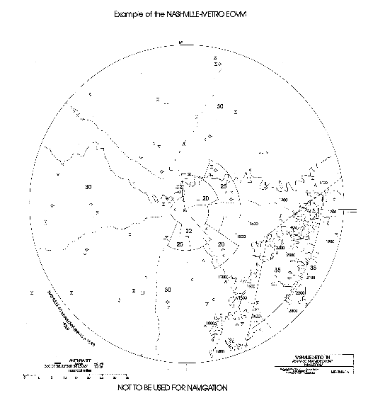
3-8-4. EMERGENCY OBSTRUCTION VIDEO MAP (EOVM)
a. An EOVM
must be established at all terminal radar facilities that have designated
mountainous areas as defined in 14 CFR Part 95, Subpart B, within their
delegated area of control and an available channel in their video mappers.
This map is intended to facilitate advisory service to an aircraft in an
emergency situation in the event an appropriate terrain/obstacle clearance
minimum altitude cannot be maintained. (See FIG 391.)
NOTE-
Appropriate terrain/obstacle clearance minimum altitudes may be defined as
MIA, MEA, Minimum Obstruction Clearance Altitude (MOCA), or MVA.
b. Alternatives,
such as combining existing maps, eliminating a lower priority map or, as a
least desirable alternative, merging the EOVM with the MVA map, must be
considered when necessary to accommodate the EOVM.
c. EOVM Use:
The EOVM must be used and the advisory service provided only when a pilot
has declared an emergency or a controller determines that an emergency
condition exists or is imminent because of the inability of an aircraft to
maintain the appropriate terrain/obstacle clearance minimum altitude/s.
d. EOVM
Design:
1. The basic
design of the EOVM must incorporate the following minimum features:
(a) Base
contour lines of the mountains with the highest peak elevation of each
depicted mountain plus 200 feet for natural low obstacle growth.
(b) Highest
elevations of adjacent topography; e.g., valleys, canyons, plateaus,
flatland, etc., plus 200 feet, or water.
(c) Prominent
man-made obstacles; e.g., antennas, power plant chimneys, tall towers,
etc., and their elevations.
(d) Satellite
airports and other airports which could serve in an emergency.
(e) MVA if
the EOVM must be merged with the MVA map for the former to be
accommodated.
(f) Other
information deemed essential by the facility.
NOTE-
To avoid clutter and facilitate maintenance, information depicted on the
EOVM should be restricted to only that which is absolutely essential.
2. All
elevations identified on the EOVM must be rounded up to the next 100-foot
increment and expressed as MSL altitudes.
NOTE-
To avoid unnecessary map clutter, the last two digits are not required.
EXAMPLE-
2=200, 57=5700, 90=9000, 132=13200
e. EOVM
Production: The preparation and procurement of the EOVM must be
accomplished in accordance with FAAO 7910.1, Aeronautical Video Map
Program.
f. EOVM
Verification: The original EOVM procurement package must be checked for
adequacy and then coordinated with the Mission Support Services, Terminal
Procedures and Charting Group through the Service Area Operations Support
Group, Flight Procedures Team (FPT) to verify the accuracy of its
information. At least once every 2 years, the EOVM must be reviewed for
adequacy and coordinated with the Terminal Procedures and Charting Group
through the FPT for accuracy.
3-8-5. ESTABLISHING DIVERSE VECTOR AREA/S (DVA)
a. DVAs may
be established at the request of the ATM and coordinated jointly with the
appropriate Service Area OSG and Mission Support Services, Terminal
Procedures and Charting Group for candidate airports within the facility's
area of jurisdiction. DVAs should be considered when an obstacle(s)
penetrates the airport's diverse departure obstacle clearance surface
(OCS). The OCS is a 40:1 surface and is intended to protect the minimum
climb gradient. If there are no obstacle penetrations of this surface,
then standard takeoff minimums apply, obstacle clearance requirements are
satisfied and free vectoring is permitted below the MVA. When the OCS is
penetrated, the Terminal Procedures and Charting Group procedural designer
will develop an obstacle departure procedure (ODP). An ODP may consist of
obstacle notes, non-standard takeoff minimums, a specified departure
route, a steeper than normal climb gradient, or any combination thereof.
If an ODP is developed for a runway, it is a candidate for a DVA. The ATM
should consider whether a DVA is desired and then consider if development
would provide operational benefits exceeding existing practices. This is
done after determining that sufficient radar coverage exists for any given
airport with a published instrument approach. When established, reduced
separation from obstacles, as provided for in TERPS diverse departure
criteria, will be used to radar vector departing IFR aircraft below the
MVA. To assist in determining if obstacles penetrate the 40:1
surface, ATMs may request the Terminal Procedures and Charting Group
provide them with a graphic depiction of any departure penetrations in
addition to completing the following steps:
1. If the
location is listed in the Terminal Procedure Publication (TPP) index,
check the take-off minimums and (Obstacle) Departure Procedures in section
C of the TPP for the DVA runway. If nothing is listed, or only obstacle
notes appear, then a DVA is not necessary. If a DP appears, development of
a DVA becomes an option.
2. If the
location is not listed, query the NFDC Web site at http://nfdc.faa.gov,
and select the Special Procedures link to determine if a “special”
instrument approach procedure exists at that airport/heliport. If there is
a special procedure, the Regional Flight Standards All Weather Office (AWO)
can supply FAA Form 8260-15A for ODP information when requested by the
facility.
NOTE-
If the TPP or AWO indicates IFR departures N/A for any given runway, then
a DVA is not authorized.
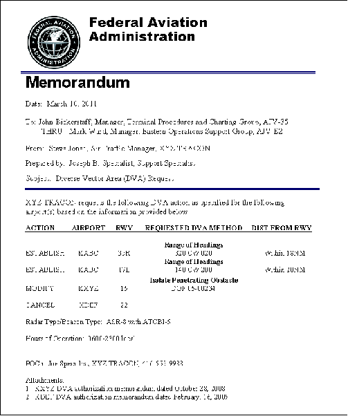
3. If the
ATM elects to request a DVA, use the sample memorandum below as a guide
(see FIG 3-8-2). Specify if the request is to establish, modify, or cancel
a DVA. If modifying or canceling a DVA, attach the memorandum that
authorizes the current DVA. The DVA request must include the following:
(a) Airport
identifier.
(b) Desired
DVA runway(s).
(c) Requested
DVA method. Specify a range of operational headings by starting from the
extreme left heading proceeding clockwise (CW) to the extreme right
heading as viewed from the departure runway in the direction of departure
(for example, Runway 36, 330 CW 030), or isolate a penetrating obstacle(s)
by identifying that obstacle(s) either by DOF number or range/bearing from
airport.
(d) Maximum
Extent (Distance) from Departure Runway.
(e) Radar
Type/Beacon Type. Provide whether the facility has an ASR-9 with Mode S
beacon system.
(f) Facility
Hours of Operation.
FIG 3-8-2
Sample DVA Memo
b. Forward DVA requests to the Terminal Procedures and Charting
Group through the appropriate Service Area OSG Manager.
c. When a
DVA is established, it will be documented and provided to the facility by
the Terminal Procedures and Charting Group on FAA Form 8260-15D, Diverse
Vector Area (DVA). The ATM must then prepare a facility directive
describing procedures for radar vectoring IFR departures below the MVA
including:
1. Textual
or graphical description of the limits of each airport's DVA for each
runway end.
2. Where
required, specific radar routes, depicted on the radar display, where
radar vectors are provided to aircraft below the MVA.
3. Free
vectoring areas, in which random vectoring may be accomplished below the
MVA.
d. IFR
aircraft climbing within a DVA must not be assigned an altitude
restriction below the MVA. When leaving the confines of the DVA, ensure
the aircraft reaches the MVA or has reported leaving the altitude of the
obstacle(s) for which the MVA was created, climbing to an altitude at
least 1,000 feet above the obstacle.
e. Headings
must not be assigned beyond those authorized by the DVA prior to reaching
the MVA.
f. Ensure
all controllers are familiar with the provisions of the facility directive
before vectoring aircraft in accordance with DVA procedures. |