Section 3. Identifying/Evaluating Aeronautical Effect
6-3-1. POLICY
a. The prime
objective of the FAA in conducting OE studies is to ensure the safety of air
navigation, and the efficient utilization of navigable airspace by aircraft.
There are many demands being placed on the use of the navigable airspace.
However, when conflicts arise concerning a structure being studied, the FAA
emphasizes the need for conserving the navigable airspace for aircraft;
preserving the integrity of the national airspace system; and protecting air
navigation facilities from either electromagnetic or physical encroachments that
would preclude normal operation.
b. In the case of
such a conflicting demand for the airspace by a proposed construction or
alteration, the first consideration should be given to altering the proposal.
c. In the case of
an existing structure, first consideration should be given to adjusting the
aviation procedures to accommodate the structure. This does not preclude issuing
a “Determination Of Hazard To Air Navigation” on an existing structure when the
needed adjustment of aviation procedures could not be accomplished without a
substantial adverse effect on aeronautical operations. In all
cases, consideration should be given to all known plans on file received by the
end of the public comment period or before issuance of a determination if the
case was not circularized.
6-3-2. SCOPE
Part 77 establishes standards for determining
obstructions to air navigation. A structure that exceeds one or more of these
standards is presumed to be a hazard to air navigation unless the aeronautical
study determines otherwise. An obstruction evaluation must identify:
a. The
effect the structure would have:
1. On
existing and proposed public-use, private use with at least one FAA-approved
instrument approach procedure, and DOD airports and/or aeronautical facilities.
2. On existing and
proposed visual flight rule (VFR)/instrument flight rule (IFR) aeronautical
departure, arrival and en route operations, procedures, and minimum flight
altitudes.
3. Regarding
physical, electromagnetic, or line-of-sight interference on existing or proposed
air navigation, communications, radar, and control systems facilities.
4. On airport
capacity, as well as the cumulative impact resulting from the structure when
combined with the impact of other existing or proposed structures.
b. Whether marking
and/or lighting is necessary.
6-3-3. DETERMINING ADVERSE EFFECT
If a structure first exceeds the obstruction
standards of Part 77, and/or is found to have physical or electromagnetic
radiation effect on the operation of air navigation facilities, then the proposed or
existing structure, if not amended, altered, or removed, has an adverse effect
if it would:
a. Require a
change to an existing or planned IFR minimum flight altitude, a published or
special instrument procedure, or an IFR departure procedure for a public-use
airport.
b. Require a VFR
operation, to change its regular flight course or altitude. This does not apply
to VFR military training route (VR) operations conducted under part 137, or
operations conducted under a waiver or exemption to the CFR.
c. Restrict the
clear view of runways, helipads, taxiways, or traffic patterns from the airport
traffic control tower cab.
d. Derogate
airport capacity/efficiency.
e. Affect future
VFR and/or IFR operations as indicated by plans on file.
f. Affect the
usable length of an existing or planned runway.
6-3-4. DETERMINING SIGNIFICANT
VOLUME OF ACTIVITY
The type of activity must
be considered in reaching a decision on the question of what volume of
aeronautical activity is “significant.” For example, if one or more aeronautical
operations per day would be affected, this would indicate regular and continuing
activity, thus a significant volume no matter what the type of operation.
However, an affected instrument procedure or minimum altitude may need to be
used only an average of once a week to be considered significant if the
procedure is one which serves as the primary procedure under certain conditions.
6-3-5. SUBSTANTIAL ADVERSE EFFECT
A proposed structure
would have, or an existing structure has, a substantial adverse effect if it
causes electromagnetic interference to the operation of an air navigation
facility or the signal used by aircraft, or if there is a combination of:
a. Adverse effect
as described in paragraph 6-3-3; and
b. A significant
volume of aeronautical operations, as described in paragraph
6-3-4, would be affected.
6-3-6. RESPONSIBILITY
The FAA's obstruction
evaluation program transcends organizational lines. In order to determine the
effect of the structure within the required notice period, each office should
forward the results of its evaluation within 15 working days to the service area
office for further processing. Areas of responsibility are delegated as follows:
a. Air traffic
personnel must:
1. Identify
when the structure exceeds Section 77.23 (a)(1) (see
FIG 6-3-1 thru FIG 6-3-6) and apply Section
77.23(b) (see
FIG 5-2-4).
2. Identify the
effect on existing and planned aeronautical operations, air traffic control
procedures, and airport traffic patterns and making recommendations for
mitigating adverse effect including marking and lighting recommendations.
3. Identify when
the structure would adversely affect published helicopter route operations as
specified in paragraph 6-3-8 subparagraph e., of this
order, and forward the case to Flight Standards.
4. Identify
whether obstruction marking/lighting are necessary and recommend the appropriate
marking and/or lighting.
5. Identify when
negotiations are necessary and conduct negotiations with the sponsor. This may
be done in conjunction with assistance from other division/service area office
personnel when their subject expertise is required (for example, in cases of
electromagnetic interference).
6. Identify when
circularization is necessary and conduct the required circularization process.
7. Evaluate all
valid aeronautical comments received as a result of the circularization and
those received as a result of the division evaluation.
8. Issue the
determination (except as noted in paragraph 7-1-2, subparagraph
b).
b. Regional
Airports Division personnel must:
1. Verify that the
airport/runway database has been reviewed, is correct, and contains all plans on
file pertaining to the OE case.
2. Identify the
structure's effect on existing and planned airports or improvements to airports
concerning airport design criteria including potential restrictions/impacts on
airport operations, capacity, efficiency and development, and making
recommendations for eliminating adverse effect. Airports Divisions are not
required to perform evaluations on OE cases that are further than 3 NM from the
Airport Reference Point (ARP) of a public-use or military airport.
3. Determine the
effect on the efficient use of airports and the safety of persons and property
on the ground. Airports will resist structures and activities that conflict with
an airport's planning, design, and/or recommendations from other
divisions/service area offices.
c. FPT personnel
must:
1. Identify when
the structure exceeds Sections 77.23(a)(3), and 77.23(a)(4).
2. Identify the
effect upon terminal area IFR operations, including transitions; radar
vectoring; holding; instrument departure procedures; any segment of a standard
instrument approach procedure (SIAP) or special SIAP, including proposed
instrument procedures and departure areas; and making recommendations for
eliminating adverse effect.
NOTE-
This paragraph applies to any IAP and Special SIAP at public-use and private-use
airports.
3. Identify the
effect on minimum en route altitudes (MEA); minimum obstruction clearance
altitudes (MOCA); minimum vectoring altitudes (MVA); minimum IFR altitudes
(MIA); minimum safe altitudes (MSA); minimum crossing altitudes (MCA); minimum
holding altitudes (MHA); turning areas and termination areas; and making
recommendations for eliminating adverse effect.
4. Coordinate with air traffic and technical operations services personnel
to determine the effect of any interference with an air navigation facility on
any terminal or en route procedure.
5. State what
adjustments can be made to the procedure/structure to mitigate or eliminate any
adverse effects of the structure on an instrument flight procedure.
d. Regional Flight
Standards personnel must identify the effect on fixed-wing and helicopter VFR
routes, terminal operations, and other concentrations of VFR traffic. When
requested by air traffic, the Flight Standards Division must also evaluate the
mitigation of adverse effect on VFR operations for marking and/or lighting of
structures.
e. Technical
Operations Services personnel must identify any electromagnetic and/or physical
effect on air navigation and communications facilities including:
1. The
presence of any electromagnetic effect in the frequency protected service volume
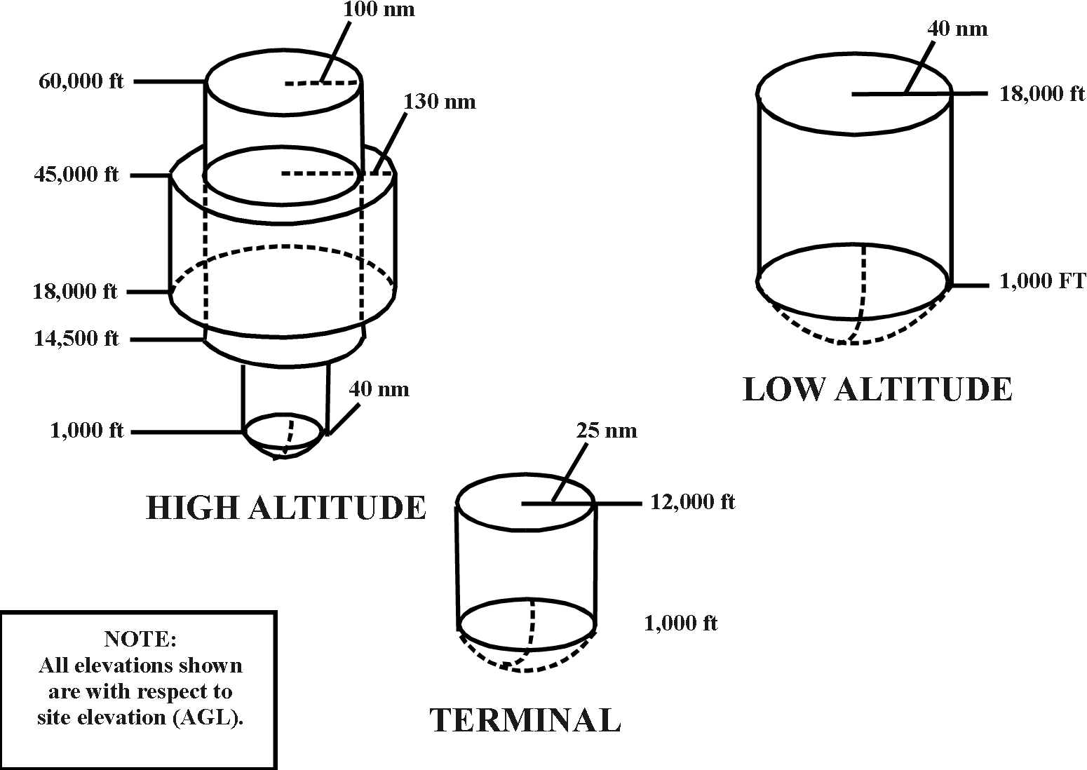
of the facilities shown in FIG 6-3-16,
FIG 6-3-17, and FIG 6-3-18.
2. The effect on
the availability or quality of navigational or communications signals to or from
aircraft including lighting systems (for example, VGSI), and making recommendations to
eliminate adverse effect.
3. The effect on
ground-based communications and NAVAID equipment, and the signal paths between
ground-based and airborne equipment, and making recommendations to eliminate
adverse effect.
4. The effect on
the availability or quality of ground-based primary and secondary radar;
direction finders; and air traffic control tower line-of-sight visibility; and
making recommendations to eliminate adverse effect.
5. The effect of
sunlight or artificial light reflections, and making recommendations to
eliminate adverse effect.
f. Military
personnel are responsible for evaluating the effect on airspace and routes used
by the military.
g. Other
applicable FAA offices or services may be requested to provide an evaluation of
the structure on a case-by-case basis.
§77.17 - Obstruction Standards.
(a)(1) - A height of 499 feet AGL at the site of the object.
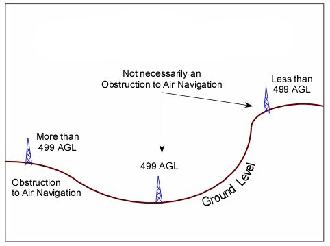
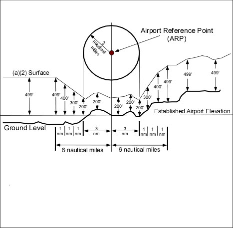
FIG 6-3-2
OBSTRUCTION STANDARDS NEAR AIRPORTS
|
Subpart C -
Obstruction Standards
§77.17(a)(2) - An object would be an
obstruction to air navigation if of greater height than 200 feet above
ground at its site, or above the established airport elevation,
whichever is higher-
(a) within 3NM of the established reference point of an airport with its
longest runway more than 3,200 feet in actual length, and
(b) that height increases in proportion of 100 feet for each additional
nautical mile from the airport reference point up to a maximum of 499
feet.
Note: Heliports excluded.
|
FIG 6-3-3
DEPARTMENT OF DEFENSE AIRPORT IMAGINARY SURFACES
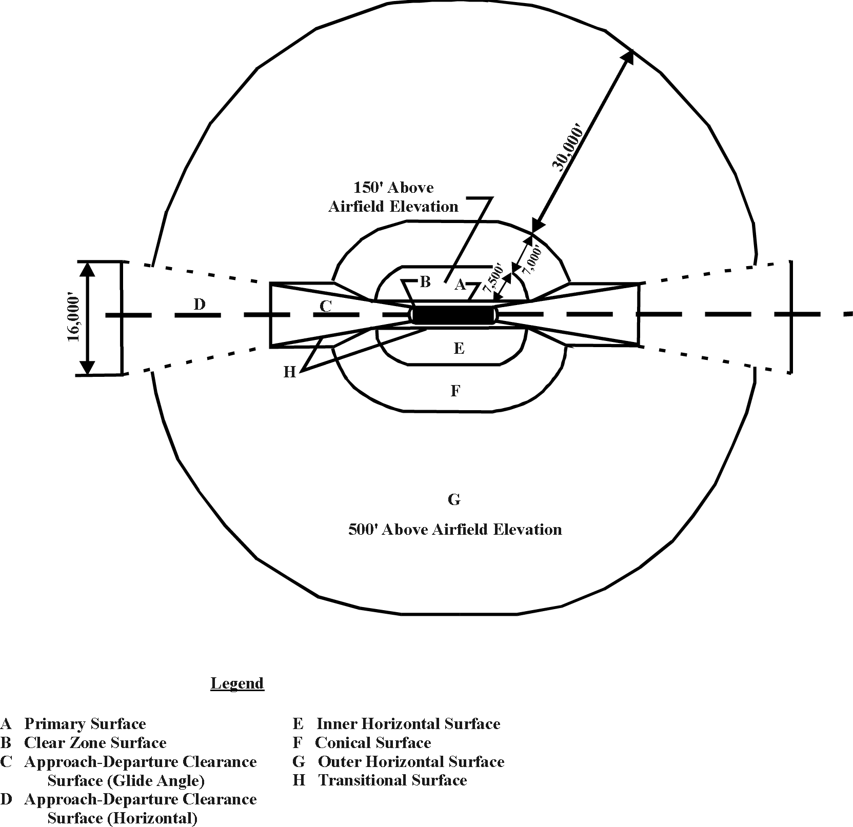
FIG 6-3-4
DEPARTMENT OF DEFENSE AIRPORT IMAGINARY SURFACES
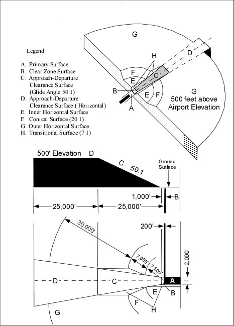
FIG 6-3-5
DEPARTMENT OF DEFENSE AIRPORT SUFACES - CLEAR ZONE
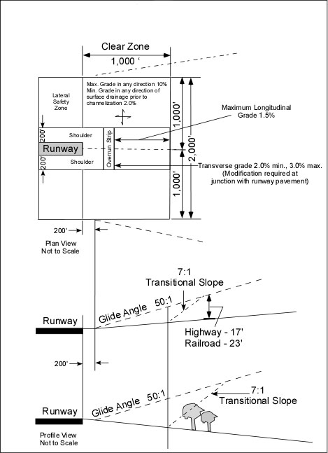
FIG 6-3-6
AIRPORT IMAGINARY SURFACES FOR HELIPORTS
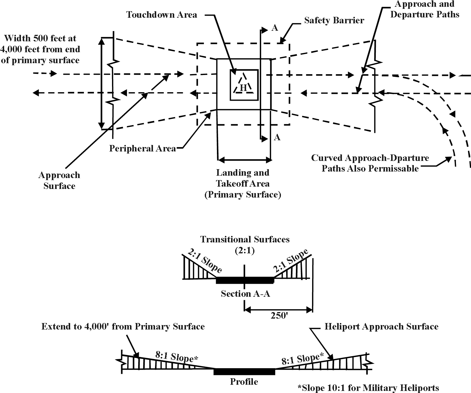
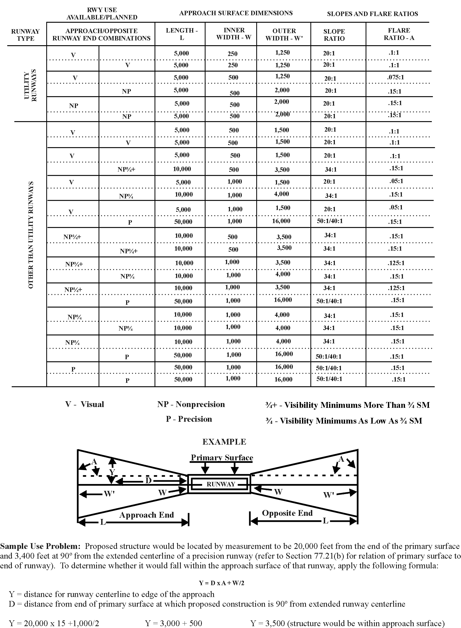
FIG 6-3-7
PART 77, APPROACH SURFACE DATA
6-3-7. AIRPORT SURFACES AND
CLEARANCE AREAS
a. CIVIL
AIRPORT SURFACES
1. Civil
airport imaginary surfaces are defined in Section 77.19 and are based on the
category of each runway according to the type of approach (visual, nonprecision,
or precision) available or planned for each runway end (see FIG 6-3-7). The appropriate runway imaginary surface
must be applied to the primary surfaces related to the physical end of the
specific runway surface that is usable for either takeoff or landing.
2. Approach
Surface Elevation - Use the runway centerline elevation at the runway threshold
and the elevation of the helipad as the elevation from which the approach
surface begins (see Sections 77.19 and 77.23).
3. Heliport
imaginary surfaces are defined in Section 77.23 and are based upon the size of
the takeoff and landing area.
4. Planned
Airport/Runway Improvements - Consider the planned runway threshold and approach
type when there is a plan on file with the FAA or with an appropriate military
service to extend the runway and/or upgrade its use or type of approach. The
existing runway threshold and type of approach may be used for temporary
structures/equipment, as appropriate.
b. DOD
AIRPORT SURFACES - The obstruction standards in Section 77.19, Civil Airport
Imaginary Surfaces, apply to civil operated joint-use airports. The obstruction
standards in Section 77.21, DOD Airport Imaginary Surfaces, are applicable only
to airports operated and controlled by a DOD service of the United States,
regardless of whether use by civil aircraft is permitted.
c. TERMINAL
OBSTACLE CLEARANCE AREA - The terminal obstacle clearance area specified in
Section 77.17(a)(3) includes the initial, intermediate, final, and missed
approach segments of an instrument approach procedure, and the circling approach
and instrument departure areas. The applicable FAA approach and departure design
criteria are contained in the 8260.3 Order series.
d. EN
ROUTE OBSTACLE CLEARANCE AREA - The en route obstacle clearance area specified
in Section 77.17(a)(4) is applicable when evaluating the effect of a structure
on an airway, a feeder route, and/or an approved off-airway route (direct route)
as prescribed in the 8260.3 Order series.
6-3-8. EVALUATING EFFECT ON VFR
OPERATIONS
a. PURPOSE.
These guidelines are for use in determining the effect of structures, whether
proposed or existing, upon VFR aeronautical operations in the navigable
airspace. The intent of these guidelines is to provide a basis for analytical
judgments in evaluating the effect of structures on VFR operations.
b. CONSIDERATIONS
1. Minimum
VFR Flight Altitudes. Minimum VFR flight altitudes are prescribed by regulation.
Generally speaking, from a VFR standpoint, the navigable airspace includes all
airspace 500 feet AGL or greater and that airspace below 500 feet required for:
(a)
Takeoff and landing, including the airport traffic pattern.
(b) Flight
over open water and sparsely populated areas (an aircraft may not be operated
closer than 500 feet to any person, vessel, vehicle, or structure).
(c)
Helicopter operations when the operation may be conducted without hazard to
persons and property on the surface.
2. VFR
Weather Minimums. Proposed or existing structures potentially have the greatest
impact in those areas where VFR operations are conducted when ceiling and/or
visibility conditions are at or near VFR weather minimums. Any structure that
would interfere with a significant volume of low altitude flights by actually
excluding or restricting VFR operations in a specific area would have a
substantial adverse effect and may be considered a hazard to air navigation.
3. Marking
and/or Lighting of Structures. Not every structure penetrating the navigable
airspace is considered to be a hazard to air navigation. Some may be marked
and/or lighted so pilots can visually observe and avoid the structures.
4. Shielded
Structures. A structure may be “shielded” by being located in proximity to other
permanent structures or terrain and would not, by itself, adversely affect
aeronautical operations (see paragraph 6-3-13).
5. Height Of Structures. Structures are of concern
to pilots during a climb after takeoff, low altitude operations, and when
descending to land. Any structure greater than 500 feet AGL, or structures of
any height which would affect landing and takeoff operations, requires extensive
evaluation to determine the extent of adverse effect on VFR aeronautical
operations.
6. Airport
Traffic Patterns. The primary concern regarding structures in airport traffic
pattern areas is whether they would create a dangerous situation during a
critical phase of flight.
7. Class
B and C Airspace. Structures that exceed obstruction standards in areas
available for VFR flight below the floor of Class B or C airspace areas require
careful evaluation. Class B and C airspace areas are designed to provide a more
regulated environment for IFR and VFR traffic in and around certain airports.
Consequently, the floors of some Class B and C areas compress VFR operations
into airspace of limited size and minimum altitude availability.
8. VFR
Routes. Pilots operating VFR frequently fly routes that follow rivers,
coastlines, mountain passes, valleys, and similar types of natural landmarks or
major highways, railroads, powerlines, canals, and other manmade structures. A
VFR route may also be comprised of specific radials of a Very High Frequency
Omnidirectional Range (VOR). These routes may correspond to an established
Federal Airway, direct radials between navigation facilities, or a single radial
providing transition to a route predicated on visual aids. While there may be
established minimum en route altitudes for segments of these routes and
navigation is dependent upon adequate signal reception, a VFR pilot may fly at
an altitude below the established minimum altitude in order to maintain visual
contact with the ground. The basic consideration in evaluating the effect of
obstructions on operations along these routes is whether pilots would be able to
visually observe and avoid them during marginal VFR weather conditions. At least
1-mile flight visibility is required for VFR operations beneath the floor of
controlled airspace. This means that a surface reference used for VFR low
altitude flight must be horizontally visible to pilots for a minimum of 1 mile.
c. EN
ROUTE OPERATIONS. The area considered for en route VFR flight begins and ends
outside the airport traffic pattern airspace area or Class B, C, and D airspace
areas.
1. A
structure would have an adverse effect upon VFR air navigation if its height is
greater than 499 feet above the surface at its site, and within 2 statute miles
of any regularly used VFR route (see FIG 6-3-8).
2. Evaluation
of obstructions located within VFR routes must recognize that pilots may, and
sometimes do, operate below the floor of controlled airspace during low ceilings
and 1-mile flight visibility. When operating in these weather conditions and
using pilotage navigation, these flights must remain within 1 mile of the
identifiable landmark to maintain visual reference. Even if made more
conspicuous by the installation of high intensity white obstruction lights, a
structure placed in this location could be a hazard to air navigation because
after sighting it, the pilot may not have the opportunity to safely
circumnavigate or overfly the structure.
3. VFR
DOD TRAINING ROUTES (VR) - Operations on VRs provide DOD aircrews low altitude,
high speed navigation and tactics training, and are a basic requirement for
combat readiness (see FAA Order 7610.4, Special Operations). Surface structures
have their greatest impact on VFR operations when ceiling and visibility
conditions are at or near basic VFR minimums. Accordingly, the guidelines for a
finding of substantial adverse effect on en route VFR operations are based on
consideration for those operations conducted under part 91 that permits flight
clear of clouds with 1 mile flight visibility outside controlled airspace. In
contrast, flight along VRs can be conducted only when weather conditions equal
or exceed 3,000 feet ceiling and 5 miles visibility. A proposed structure's
location on a VR is not a basis for determining it to be a hazard to air
navigation; however, in recognition of the DOD's requirement to conduct low
altitude training, disseminate Part 77 notices and aeronautical study
information to DOD representatives. Additionally, attempt to persuade the
sponsor to lower or relocate a proposed structure that exceeds obstruction
standards and has been identified by the DOD as detrimental to its training
requirement.
d. AIRPORT
AREAS - Consider the following when determining the effect of structures on VFR
operations near airports:
1. Traffic
Pattern Airspace - There are many variables that influence the establishment of
airport arrival and departure traffic flows. Structures in the traffic pattern
airspace may adversely affect air navigation by being a physical obstruction to
air navigation or by distracting a pilot's attention during a critical phase of
flight. The categories of aircraft using the airport determine airport traffic
pattern airspace dimensions.
(a)
Traffic Pattern Airspace dimensions (See FIG 6-3-9).
(b) Within
Traffic Pattern Airspace - A structure that exceeds a 14 CFR, Part 77
obstruction standard and that exceeds any of the following heights is considered
to have an adverse effect and would have a substantial adverse effect if a
significant volume of VFR aeronautical operations are affected except as noted
in paragraph 6-3-8
d.1.(f)
and (g) (see FIG 6-3-10).
(c) The
height of the transition surface (other than abeam the runway), the approach
slope (up to the height of the horizontal surface), the horizontal surface, and
the conical surface (as applied to visual approach runways, Section 77.19).
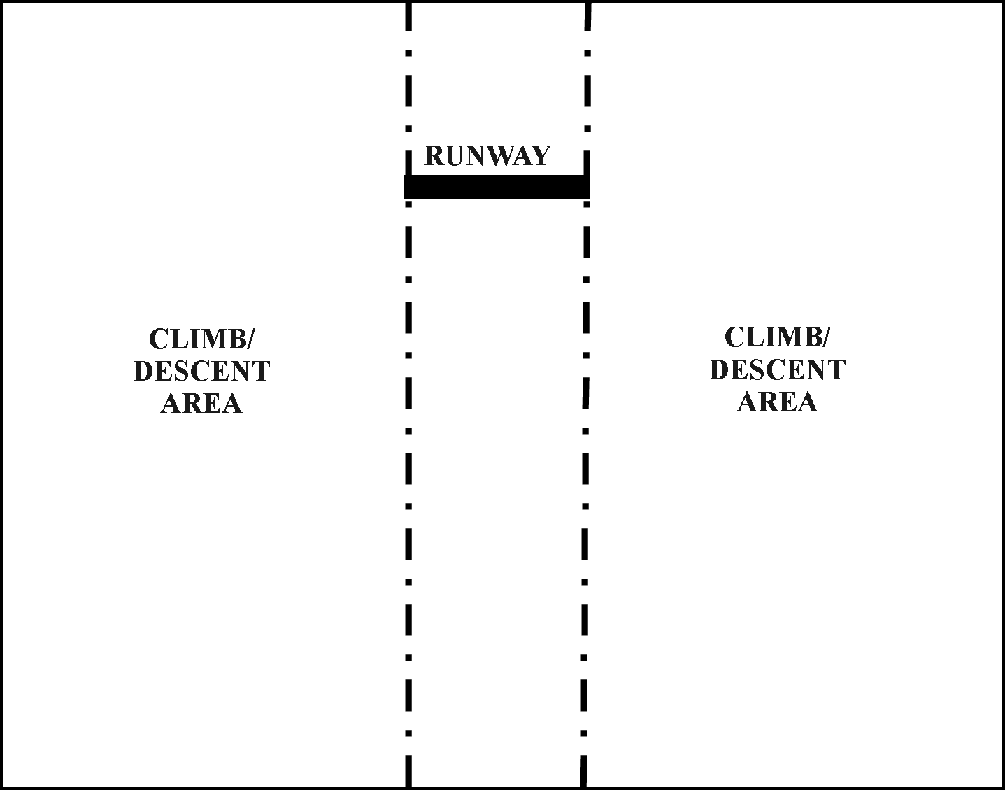
(d) Beyond
the lateral limits of the conical surface and in the climb/descent area - 350
feet above airport elevation or the height of 14 CFR Section 77.17(a)(2),
whichever is greater not to exceed 499 feet above ground level (AGL). The
climb/descent area begins abeam the runway threshold being used and is the area
where the pilot is either descending to land on the runway or climbing to
pattern altitude after departure. (The area extending outward from a line
perpendicular to the runway at the threshold, see FIG
6-3-11).
(e) Beyond
the lateral limits of the conical surface and not in the climb/descent area of
any runway - 499 feet above airport elevation (AE) not to exceed 499 feet AGL.
(f) An
existing structure (that has been previously studied by the FAA), terrain, or a
proposed structure (that would be shielded by existing structures) may not be
considered to have a substantial adverse effect. In such instances, the traffic
pattern may be adjusted as needed on a case-by-case basis.
(g) Exceptions
may be made on a case-by-case basis when the surrounding terrain is
significantly higher than the airport elevation, the established traffic pattern
altitude is less than 800 feet above airport elevation or “density altitude” is
a consideration.
2. Terminal
Transition Routes - A structure would have an adverse effect upon VFR air
navigation if it:
(a) Exceeds
a height of 499 feet above the surface at its site; and
(b) Is
located within 2 statute miles of the centerline of any regularly used VFR route
(see FIG 6-3-8).
3. VFR
Approach Surface Slope Ratios - A structure would have an adverse effect upon
VFR air navigation if it penetrates the approach surface slope of any runway.
The following slope ratios are applied to the end of the primary surface:
(a) 20:1
for civil visual approaches.
(b) 50:1
for DOD runway approaches.
(c) 8:1
for civil helicopter approaches surfaces.
(d) 10:1
for DOD helicopter approach surfaces.
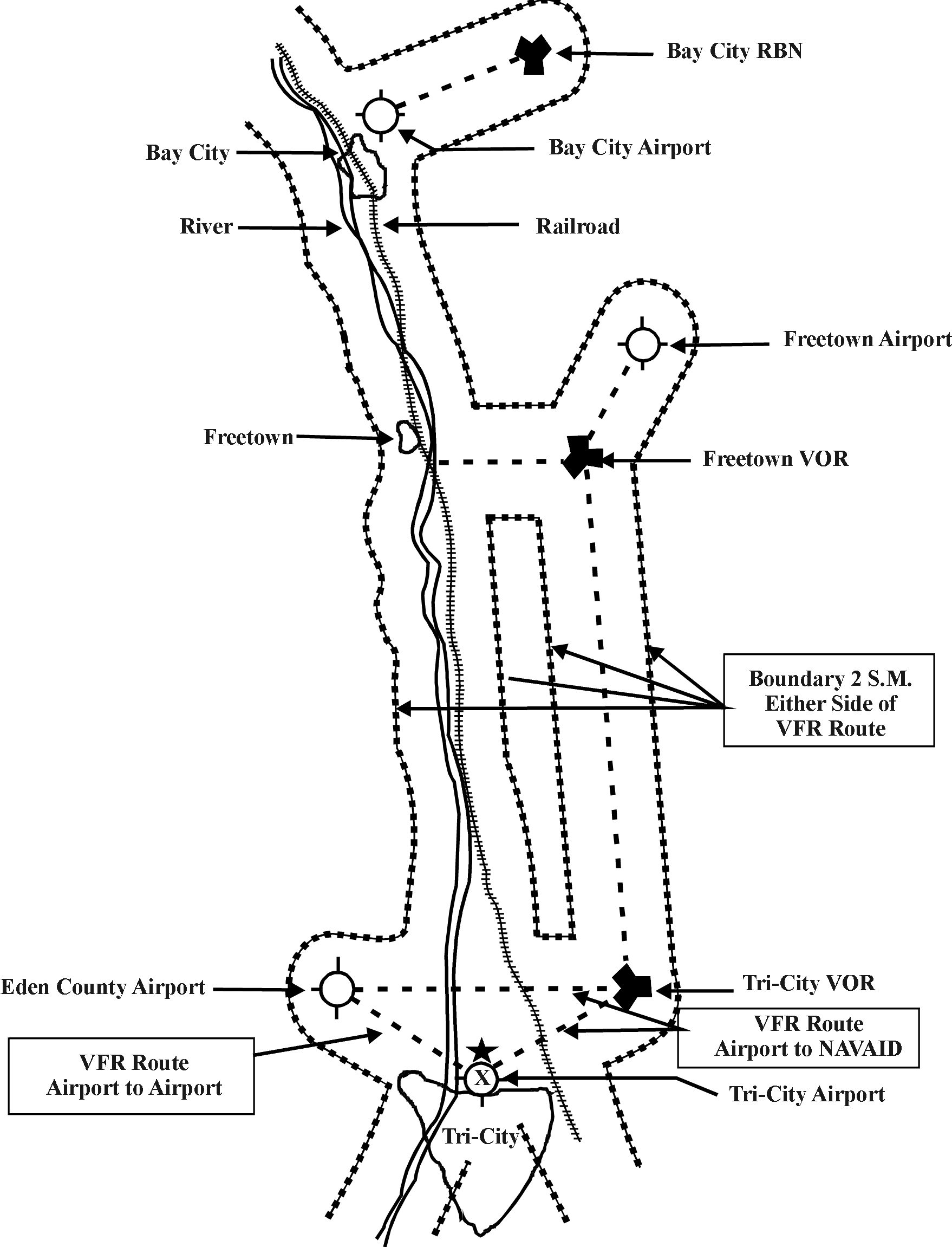
FIG 6-3-9
TRAFFIC PATTERN AIRSPACE
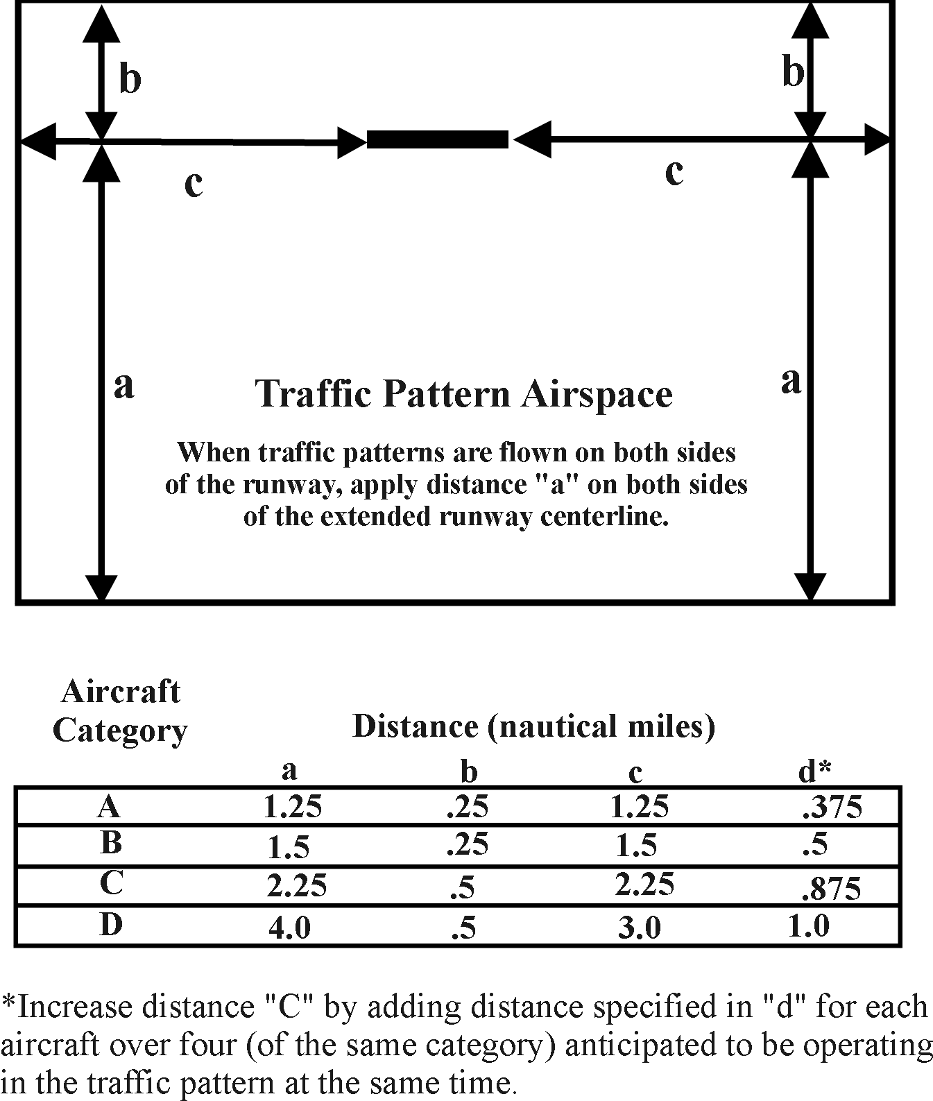
FIG 6-3-10
TRAFFIC PATTERN AIRSPACE ADVERSE EFFECT
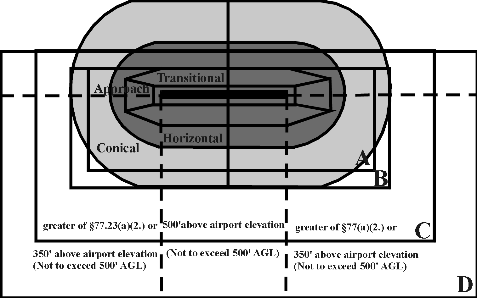
FIG 6-3-11
TRAFFIC PATTERN AIRSPACE CLIMB/DESCENT AREAS
e. HELICOPTERS - The special maneuvering
characteristics of helicopters are recognized in Sections 91.119 and 91.155,
provided operations are conducted without hazard to persons or property on the
ground. Helicopter pilots must also operate at a speed that will allow them to
see and avoid obstructions. Consequently, proposed or existing structures are
not considered factors in determining adverse effect upon helicopter VFR
operations except as follows:
1. En
route. When the Administrator prescribes routes and altitudes for helicopters,
the exemptions to part 91 for helicopters do not apply. Thus, any structure
would have an adverse effect if it penetrates an imaginary surface 300 feet
below an established helicopter minimum flight altitude and is located within
250 feet either side of the established route's centerline.
2. Heliport
Landing/Takeoff Area. Any structure would have an adverse effect if it would
exceed any of the heliport imaginary surfaces. Although helicopter
approach-departure paths may curve, the length of the approach-departure surface
remains fixed.
f. AGRICULTURAL
AND INSPECTION AIRCRAFT OPERATIONS - Rules that apply to agricultural dispensing
operations, as prescribed in part 137, allow deviation from part 91 altitude
restrictions. It is the pilot's responsibility to avoid obstacles because the
agricultural operations must be conducted without creating a hazard to persons
or property on the surface. Similar operations include pipeline, power line, and
military low-level route inspections. Consequently, these operations are not
considered in reaching a determination of substantial adverse effect.
NOTE-
Before and after the dispensing is completed, the pilot is required to operate
under the part 91 minimum altitudes.
g. OPERATIONS
UNDER WAIVER OR EXEMPTION TO CFR - Waivers and/or exemptions to CFR operating
rules include provisions to ensure achievement of a level of safety equivalent
to that which would be present when complying with the regulation waived or
exempted. Additionally, waivers and exemptions do not relieve pilots of their
responsibility to conduct operations without creating a hazard to persons and
property on the surface. Accordingly, a determination of hazard to air
navigation must not be based upon a structure's effect on aeronautical
operations conducted under a waiver or exemption to CFR operating rules.
6-3-9. EVALUATING EFFECT ON IFR OPERATIONS
a. PURPOSE.
This section provides general guidelines for determining the effect of
structures, whether proposed or existing, upon IFR aeronautical operations.
b. STANDARDS.
Obstruction standards are used to identify potential adverse effects and are not
the basis for a determination. The criteria used in determining the extent of
adverse affect are those established by the FAA to satisfy operational,
procedural, and electromagnetic requirements. These criteria are contained in
regulations, advisory circulars, and orders (for example, the 8260 Order series
and FAA Order 7110.65). Obstruction evaluation personnel must apply these
criteria in evaluating the extent of adverse effect to determine if the
structure being studied would actually have a substantial adverse effect and
would constitute a hazard to air navigation.
c. IFR
MINIMUM FLIGHT ALTITUDES. Technical Operations Aviation System Standards is the
principal FAA element responsible for establishing instrument procedures and
minimum altitudes for IFR operations. FPT personnel must evaluate the effect of
proposed structures on IFR aeronautical operations as outlined in Order 8260.19,
Flight Procedures and Airspace.
d. EN
ROUTE IFR OPERATIONS
1. Minimum
En Route Altitudes (MEA). MEAs are established for each segment of an airway or
an approved route based upon obstacle clearance, navigational signal reception,
and communications. The MEA assures obstruction clearance and acceptable
navigational signal coverage over the entire airway or route segment flown. Any
structure that will require an MEA to be raised has an adverse effect. Careful
analysis by the appropriate Flight Procedures Team and air traffic personnel is
necessary to determine if there would be a substantial adverse effect on the
navigable airspace. Generally, the loss of a cardinal altitude is considered a
substantial adverse effect. However, the effect may not be substantial if the
aeronautical study discloses that the affected MEA is not normally flown by
aircraft, nor used for air traffic control purposes.
2. Minimum Obstruction Clearance Altitudes (MOCA).
MOCAs assure obstacle clearance over the entire route segment to which they
apply and assure navigational signal coverage within 22 NM of the associated VOR
navigational facility. For that portion of the route segment beyond 22 NM from
the VOR, where the MOCA is lower than the MEA and there are no plans to lower
the MEA to the MOCA, a structure that affects only the MOCA would not be
considered to have substantial adverse effect. Other situations require study as
ATC may assign altitudes down to the MOCA under certain conditions.
3. Minimum
IFR Altitudes (MIA). These altitudes are established in accordance with Order
7210.37, En Route Minimum IFR Altitude Sector Charts, to provide the controller
with minimum IFR altitude information for off-airway operations. MIAs provide
the minimum obstacle clearance and are established without respect to
flight-checked radar or normal radar coverage. Any structure that would cause an
increase in a MIA is an obstruction, and further study is required to determine
the extent of adverse effect. Radar coverage adequate to vector around such a
structure is not, of itself, sufficient to mitigate a finding of substantial
adverse effect that would otherwise be the basis for a determination of hazard
to air navigation.
4. IFR
Military Training Routes (IR's) - Operations on IR's provide pilots with
training for low altitude navigation and tactics (see FAA Order 7610.4, Special
Operations). Flight along these routes can be conducted below the minimum IFR
altitude specified in part 91, and the military conducts operational flight
evaluations of each route to ensure compatibility with their obstructions
clearance requirements. A proposed structure's location on an IR is not a basis
for determining it to be a hazard to air navigation; however, in recognition of
the military's requirement to conduct low altitude training, disseminate Part 77
notices and aeronautical study information to military representatives.
Additionally, attempt to persuade the sponsor to lower, or relocate proposed
structures that exceed obstruction standards and have been identified by the
military as detrimental to their training requirement.
5. Radar
Bomb Sites (RBS) - These sites are a vital link in the low level training
network used by the U.S. Air Force to evaluate bomber crew proficiency. They
provide accurate radar records for aircraft flying at low altitudes attacking
simulated targets along the RBS scoring line. An obstruction located within the
flights' RBS boundaries may have a substantial adverse effect and a serious
operational impact on military training capability.
e. TERMINAL
AREA IFR OPERATIONS. The obstruction standards contained in part 77 are also
used to identify obstructions within terminal obstacle clearance areas. Any
structure identified as an obstruction is considered to have an adverse effect;
however, there is no clear-cut formula to determine what extent of adverse
effect is considered substantial. Instrument approach and departure procedures
are established in accordance with published obstacle clearance guidelines and
criteria. However, there are segments of instrument approach procedures where
the minimum altitudes may be revised without substantially effecting landing
minimums. Thus, the determination must represent a decision based on the best
facts that can be obtained during the aeronautical study.
1. Instrument
Approach Procedures (IAP)/Special SIAP. Flight Procedures Team personnel are
responsible for evaluating the effect of structures upon any segment of an
IAP/Special SIAP, any proposed IAP/Special SIAP, or any departure restriction.
However, all FAA personnel involved in the obstruction evaluation process should
be familiar with all aspects of the terminal area IFR operations being
considered. If Flight Procedures Team personnel determine that a structure will
affect instrument flight procedures, their evaluation should include those
procedural adjustments that can be made without adversely affecting IFR
operations. When the study discloses that procedural adjustments to reduce or
mitigate any adverse effect cannot be accomplished, then the comments to air
traffic must identify the significance of this effect on procedures and
aeronautical operations.
NOTE-
This paragraph applies to any IAP and Special SIAP at public-use and private-use
airports.
2. Minimum
Vectoring Altitudes (MVA). These altitudes are based upon obstruction clearance
requirements only (see Order 8260.19). The area considered for obstacle
clearance is the normal operational use of the radar without regard to the
flight-checked radar coverage. It is the responsibility of individual
controllers to determine that a target return is adequate for radar control
purposes. MVAs are developed by terminal facilities, approved by the Terminal
Procedures and Charting Group and published for controllers on MVA Sector
Charts. Any structure that would cause an increase in an MVA is an obstruction
and a study is required to determine the extent of adverse effect. Radar
coverage adequate to vector around such a structure is not, of itself,
sufficient to mitigate a finding of substantial adverse effect that would
otherwise be the basis for a determination of hazard to air navigation.
3. Military Airports. With the exception of the U.S.
Army, the appropriate military commands establish and approve terminal
instrument procedures for airports under their respective jurisdictions.
Consequently, the OEG must ensure that the military organizations are provided
the opportunity to evaluate a structure that may affect their operations. While
the military has the responsibility for determining the effect of a structure,
it is expected that the FPT will assist air traffic in reconciling differences
in the military findings.
4. Departure
Procedures. TERPS, Chapter 12, Civil Utilization of Area Navigation (RNAV)
Departure Procedures, contains criteria for the development of IFR departure
procedures. An obstacle that penetrates the 40:1 departure slope is considered
to be an obstruction to air navigation. Further study is required to determine
if adverse effect exists. Any proposed obstacle that penetrates the 40:1
departure slope, originating at the departure end of runway (DER) by up to 35
feet will be circularized. If an obstacle penetrates the 40:1 departure slope by
more than 35 feet, it is presumed to be a hazard, and a Notice of Presumed
Hazard will be issued, and processed accordingly. Analysis by the Terminal
Procedures and Charting Group and air traffic personnel is necessary to
determine if there would be a substantial adverse effect on the navigable
airspace.
5. Minimum
Safe Altitudes (MSA). A MSA is the minimum obstacle clearance altitude for
emergency use within a specified distance from the navigation facility upon
which a procedure is predicated. These are either Minimum Sector Altitudes,
established for all procedures within a 25-mile radius of the navigational
facility (may be increased to 30 miles under certain conditions), or Emergency
Safe Altitudes, established within a 100-mile radius of the navigation facility
and normally used only in military procedures at the option of the approval
authority. These altitudes are designed for emergency use only and are not
routinely used by pilots or by air traffic control. Consequently, they are not
considered a factor in determining the extent of adverse effect, used as the
basis of a determination, or addressed in the public notice of an aeronautical
study.
f. CONSIDERING
ACCURACY. Experience has shown that submissions often contain elevation and/or
location errors. For this reason, the Flight Procedures Team uses vertical and
horizontal accuracy adjustments, as reflected below, to determine the effect on
IFR operations.
1. Accuracy
Application - Current directives require the FPT to apply accuracy standards to
obstacles when evaluating effects on instrument procedures. These accuracy
standards typically require an adjustment of 50 feet vertically and 250 feet
horizontally to be applied in the most critical direction. Normally, these
adjustments are applied to those structures that may become the controlling
obstructions and are applicable until their elevation and location are verified
by survey.
2. Certified
Accuracy - The FPT must notify air traffic whenever certified accuracy is needed
to determine if the structure will have an adverse effect. Air traffic must then
contact the sponsor to request a surveyed verification of the elevation and
location. The acceptable accuracy verification method must be provided and
certified by a licensed engineer or surveyor. The survey must include the plus
or minus accuracy required by the FPT, as well as the signature of the
engineer/surveyor and the appropriate seal.
3. Determination
- A final determination based on improved accuracy must not be issued until
after the certified survey is received and evaluated.
4.
Survey Information Distribution - When the certified survey is received, Air
Traffic personnel must ensure that the survey information is provided to FPT
personnel and must send to AeroNav a copy of the survey attached to the FAA Form
7460-2, Notice of Actual Construction or Alteration.
6-3-10. EVALUATING EFFECT ON
AIR NAVIGATION AND COMMUNICATION FACILITIES
a. The
FAA is authorized to establish, operate, and maintain air navigation and
communications facilities and to protect such facilities from interference.
During evaluation of structures, factors that may adversely affect any portion
or component of the NAS must be considered. Since an electromagnetic
interference potential may create adverse effects as serious as those caused by
a physical penetration of the airspace by a structure, those effects must be
identified and stated. Proposals will be handled, when appropriate, directly
with FCC through Spectrum Assignment and Engineering Services.
b. Technical
operations services personnel must evaluate notices to determine if the
structure will affect the performance of existing or proposed NAS facilities.
The study must also include any plans for future facilities, proposed airports,
or improvements to existing airports.
c. The
physical presence of a structure and/or the electromagnetic signals emanating or
reflecting there from may have a substantial adverse effect on the availability,
or quality of navigational and communications signals, or on air traffic
services needed for the safe operation of aircraft. The following general
guidelines are provided to assist in determining the anticipated interference.
1. Instrument
Landing System (ILS) - Transmitting antennas are potential sources of
electromagnetic interference that may effect the operation of aircraft using an
ILS facility. The antenna height, radiation pattern, operating frequency,
effective radiated power (ERP), and its proximity to the runway centerline are
all factors contributing to the possibility of interference. Normally, any
structure supporting a transmitting antenna within the established localizer
and/or glide-slope service volume area must be studied carefully. However,
extremes in structure height, ERP, frequency, and/or antenna radiation pattern
may require careful study of structures up to 30 NM from the ILS frequency's
protected service volume area.
(a) ILS
Localizer. Large mass structures adjacent to the localizer course and/or antenna
array are potential sources of reflections and/or re-radiation that may affect
facility operation. The shape and intensity of such reflections and/or
re-radiation depends upon the size of the reflecting surface and distance from
the localizer antenna. The angle of incidence reflection in the azimuth plane
generally follows the rules of basic optical reflection. Normally, in order to
affect the course, the reflections must come from structures that lie in or near
the on-course signal. Large mass structures of any type, including metallic
fences or powerlines, within plus/minus 15 degrees of extended centerline up to
1 NM from the approach end of the runway and any obstruction within 500 feet of
the localizer antenna array must be studied carefully. (Refer to FAA Order
6750.16, Siting Criteria for Instrument Landing Systems).
(b)
ILS Glide Slope. Vertical surfaces within approximately 1,000 feet of the runway
centerline and located up to 3,000 feet forward of the glide slope antenna can
cause harmful reflections. Most interference to the glide slope are caused by
discontinuities in the ground surface, described approximately as a rectangular
area 1,000 feet wide by 5,000 feet long, extending forward from the glide slope
antenna and centered at about the runway centerline. Discontinuities are usually
in the form of rough terrain or buildings (refer to FAA Order 6750.16, Siting
Criteria for Instrument Landing Systems).
2. Microwave
Landing System (MLS). The guidelines stated for ILS systems above also apply to
MLS installations. The established MLS service volume defines the area of
concern.
3. Very
High Frequency Omni-Directional Radio Range and Tactical Air Navigation Aid
(VOR/TACAN). Usually, there should be no reflecting structures or heavy
vegetation (trees, brush, etc.) within a 1,000 foot radius of the VOR or the
TACAN antenna. Interference may occur from large structures or powerlines up to
2 NM from the antenna. Wind turbines are a special case, in that they may cause
interference up to 8 NM from the antenna. (Refer to FAA Order 6820.10, VOR,
VOR/DME, and TACAN Siting Criteria).
4. Air
Route Surveillance Radar/Airport Surveillance Radar (ARSR/ASR). Normally, there
should be no reflecting structures within a 1,500-foot radius of the radar
antenna. In addition, large reflective structures up to 3 NM from the antenna
can cause interference unless they are in the “shadow” of topographic features.
Wind turbines are a special case, in that they may cause interference up to the
limits of the radar line of site.
5. Air Traffic Control Radar Beacon (ATCRB). The
effects encountered due to reflections of the secondary radar main lobe are more
serious than those associated with primary radar. Therefore, it is necessary to
ensure that no large vertical reflecting surface penetrates a 1,500-foot radius
horizontal plane located 25 feet below the antenna platform. In addition,
interference may occur from large structures up to 12 miles away from the
antenna. This distance will depend on the area of the reflecting surface, the
reflection coefficient of the surface, and its elevation with respect to the
interrogator antenna. (Refer to FAA Order 6310.6, Primary/Secondary Terminal
Radar Siting Handbook).
6. Directional
Finder (DF). The DF antenna site should be free of structures that will obstruct
line-of-sight with aircraft at low altitudes. The vicinity within 300 feet of
the antenna should be free of metallic structures which can act as re-radiators.
7. Communication
Facilities. Minimum desirable distances to prevent interference problems between
communication facilities and other construction are:
(a) 1,000
feet from power transmission lines (other than those serving the facility) and
other radio or radar facilities.
(b) 300
feet from areas of high vehicle activity such as highways, busy roads, and large
parking areas.
(c) One
(1) NM from commercial broadcasting stations (e.g., FM, TV).
8. Approach
Lighting System. No structure, except the localizer antenna, the localizer far
field monitor antenna, or the marker antenna must protrude above the approach
light plane. For approach light plane clearance purposes, all roads, highways,
vehicle parking areas, and railroads must be considered as vertical solid
structures. The clearance required above interstate highways is 17 feet; above
railroads, 23 feet; and for all other public roads, highways, and vehicle
parking areas, 15 feet. The clearance required for a private road is 10 feet or
the highest mobile structure that would normally use the road, which would
exceed 10 feet. The clearance for roads and highways must be measured from the
crown of the road; the clearance for railroads must be measured from the top of
the rails. For vehicle parking areas, clearance must be measured from the
average grade in the vicinity of the highest point. Relative to airport service
roads substantial adverse effect can be eliminated if all vehicular traffic is
controlled or managed by the air traffic control facility. A clear line-of-sight
is required to all lights in the system from any point on a surface, one-half
degree below the aircraft descent path and extending 250 feet each side of the
runway centerline, up to 1,600 feet in advance of the outermost light in the
system. The effect of parked or taxiing aircraft must also be considered when
evaluating line-of-sight for approach lighting systems.
9. Visual
Approach Slope Indicator (VASI)/Precision Approach Path Indicator (PAPI). No
structures or obstructions must be placed within the clearance zone for the
particular site involved or the projected visual glide path.
NOTE-
VASI and PAPA now fall under the heading of VGSI.
10. Runway
End Identifier Lights (REIL). No structures or obstructions must be placed
within the established clearance zone.
d. Factors
that modify the evaluation criteria guidelines require consideration. Some
facility signal areas are more susceptible to interference than others. The
operational status of some signals may already be marginal because of existing
interference from other structures. In addition, the following characteristics
of structures must be considered:
1. The
higher the structure's height is in relation to the antenna, the greater the
chance of interfering reflections. Any structure subtending a vertical angle
greater than one degree from the facility is usually cause for concern. Tall
structures, such as radio towers and grain elevators, can interfere from
distances greater than those listed in the general criteria.
2. The
type of construction material on the reflecting surface of the structure is a
factor, with nonmetallic surfaces being less troublesome than metallic or
metallic impregnated glass.
3. Aircraft
hangars with large doors can be a special problem because the reflecting surface
of the hangar varies appreciably with changes in the position of the doors.
4. Interference is usually caused by mirror
reflections from surfaces on the structure. Orientation of the structure
therefore plays an important part in the extent of the interference. Reflections
of the largest amplitude will come from signals striking a surface perpendicular
to the signals. Signals striking a surface at a shallow angle will have a
smaller amplitude.
e. Air
traffic personnel must request technical operations services personnel to assist
them in discussions with sponsors to explore alternatives to resolve the
prospective adverse effects to facilities. These may involve design revisions,
relocation, or reorientation depending on the character of the construction and
facility involved.
f. Attempt
to resolve electromagnetic interference (EMI) before issuing a hazard
determination. Notify the sponsor by letter (automated DPH letter) that the
structure may create harmful EMI and include in the letter the formula and
values that were applied, the specific adverse effects expected, and an offer to
consider alternatives. Provide the sponsor, as well as the FAA, ample time to
exhaust all available avenues for positive resolution. The intent of this
process is to allow the sponsor adequate time to consider the problems and the
alternatives before a decision is rendered by the issuance of the FAA
determination. Follow these guidelines in all situations where harmful EMI is
projected by the study.
6-3-11. EVALUATING PLANNED OR
FUTURE AIRPORT DEVELOPMENT PROGRAMS
The national system of airports consists of
public, civil, and joint-use airport facilities considered necessary to
adequately meet the anticipated needs of civil aeronautics. Airport Planning and
Programming Offices are the most accurate sources of up-to-date information on
airport development plans. Consequently, Airports personnel are expected to
extensively review structures in reference to the safe and orderly development
of airport facilities, including what development will realistically be
accomplished within a reasonable time. Areas of consideration in accomplishing
this responsibility are:
a. Future
Development of Existing Airports. A detailed review in this area requires
looking at current planned airport projects, national airport plan data, and
land-use planning studies in the vicinity of the structure. The results of the
study forwarded to air traffic must include appropriate comments regarding the
extent of Federal aid, sponsor airport investments, the airport owner's
obligations in existing grant-in-aid agreements, and anticipated aeronautical
activity at the airport and in the general area. If a structure would adversely
impact an airport's efficiency, utility, or capacity, the responsible Airports
Office should document this impact in its evaluation. Comments should include
recommended new location(s) for the structure as appropriate.
b. New
Airport Development. When a structure requiring notice under Part 77 and any new
airport development are both in the same vicinity, Airports personnel must study
the interrelationship of the structure and the airport. Additionally,
supplemental information on the proposed airport site must be furnished to the
OEG. If a substantial adverse effect is anticipated, Airports personnel must
provide detailed comments and specific recommendations for mitigating the
adverse effects.
6-3-12. EVALUATING TEMPORARY CONSTRUCTION
a. Temporary
Construction Equipment. Construction of structures normally requires use of
temporary construction equipment that is of a greater height than the proposed
structure. Appropriate action is necessary to ensure that the temporary
construction equipment does not present a hazard to air navigation. It is not
possible to set forth criteria applicable to every situation; however, the
following action examples may help to minimize potential problems:
1. If
use of the temporary construction equipment is on an airport, it may be
necessary to negotiate with airport managers/owners to close a runway, taxiway,
temporarily move a runway threshold, or take other similar action.
2. Negotiate
with equipment operators to raise and lower cranes, derricks, or other
construction equipment when weather conditions go below predetermined minimums
as necessary for air traffic operations or as appropriate for the airport
runways in use.
3. Control the movement of construction vehicle
traffic on airports.
4. Adjust
minimum IFR altitudes or instrument procedures as necessary to accommodate the
construction equipment if such action will not have serious adverse effects on
aeronautical operations.
5. Request
that the temporary construction equipment be properly marked and/or lighted if
needed.
b. Temporary
Structures - OE notices for temporary structures are processed in the same
manner as a permanent structure, but require special consideration in
determining the extent of adverse effect. This is especially true of structures
such as cranes and derricks that may only be at a particular site for a short
time period. As a general policy, it is considered in the public interest to
make whatever adjustments necessary to accommodate the temporary structure of 30
days or less if there is no substantial adverse affect on aeronautical
operations or procedures. However, this policy does not apply if the
aeronautical study discloses that the structure would be a hazard to aviation.
Reasonable adjustments in aeronautical operations and modifications to the
temporary structure should be given equal consideration.
6-3-13. CONSIDERING SHIELDING
Shielding as described below should not be
confused with notice criteria as stated in Section 77.9(e).
a. Consideration.
Shielding is one of many factors that must be considered in determining the
physical effect a structure may have upon aeronautical operations and
procedures. Good judgment, in addition to the circumstances of location and
flight activity, will influence how this factor is considered in determining
whether proposed or existing structures would be physically shielded.
b. Principle.
The basic principle in applying the shielding guidelines is whether the location
and height of the structures are such that aircraft, when operating with due
regard for the shielding structure, would not collide with that structure.
c. Limitations.
Application of the shielding effect is limited to:
1. The
physical protection provided by existing natural terrain, topographic features,
or surface structures of equal or greater height than the structure under study;
and
2. The
structure(s) providing the shielding protection is/are of a permanent nature and
there are no plans on file with the FAA for the removal or alteration of the
structure(s).
d. Guidelines.
Any proposed construction of or alteration to an existing structure is normally
considered to be physically shielded by one or more existing permanent
structure(s), natural terrain, or topographic feature(s) of equal or greater
height if the structure under consideration is located:
1. Not
more than 500 feet horizontal distance from the shielding structure(s) and in
the congested area of a city, town, or settlement, provided the shielded
structure is not located closer than the shielding structures to any heliport or
airport located within 5 miles of the structure(s).
2. Such
that there would be at least one such shielding structure situated on at least
three sides of the shielded structure at a horizontal distance of not more than
500 feet.
3. Within
the lateral dimensions of any runway approach surface but would not exceed an
overall height above the established airport elevation greater than that of the
outer extremity of the approach surface, and located within, but would not
penetrate, the shadow plane(s) of the shielding structure(s).
e. OEG
must coordinate with FPT before applying shielding criteria for precision
approach surface penetrations.
NOTE-
See FIG 6-3-7 and FIG
6-3-12.
6-3-14. CONSIDERING SHADOW PLANE
The term “shadow plane” means a surface
originating at a horizontal line passing through the top of the shielding
structure at right angles to a straight line extending from the top of the
shielding structure to the end of the runway. The shadow plane has a width equal
to the projection of the shielding structure's width onto a plane normal to the
line extending from the top and center of the shielding structure to the
midpoint of the runway end. The shadow plane extends horizontally outward away
from the shielding structure until it intersects or reaches the end of one of
the imaginary approach area surfaces; see FIG 6-3-13,
FIG 6-3-14, and FIG 6-3-15.
6-3-15. RECOMMENDING MARKING
AND LIGHTING OF STRUCTURES
a. STANDARDS.
FAA standards, procedures, and types of equipment specified for marking and
lighting structures are presented in AC 70/7460-1, Obstruction Marking and
Lighting. These standards provide a uniform means to indicate the presence of
structures and are the basis for recommending marking and lighting to the
public. These standards are the minimum acceptable level of conspicuity to warn
pilots of the presence of structures. They must also apply when Federal funds
are to be expended for the marking and lighting of structures.
b. AERONAUTICAL
STUDY. All aeronautical studies must include an evaluation to determine whether
obstruction marking and/or lighting are necessary and to what extent. The entire
structure or complex, including closely surrounding terrain and other
structures, must be considered in recommending marking and lighting. A
subsequent study may indicate a need to change an earlier determination by
recommending marking and/or lighting when such recommendation was not made in
the original study or, in some cases, after a determination was issued.
1. Proposed
Structures. A change in runway length or alignment, a new airport development
project, a change in aeronautical procedures, or other similar reasons may be
cause for additional study of proposed structures to determine whether marking
and/or lighting are now appropriate even when not recommended in the original
study.
2. Existing
Structures. A marking and/or lighting recommendation may be made at any time. In
making the recommendation consider changes that have occurred in the vicinity of
the structure since the initial determination was made and include such factors
as increased aircraft activity, the closing of an airport, changes in IFR and
VFR routes, and shielding by taller structures.
c. RECOMMENDATIONS.
Recommend the marking and/or lighting standard most appropriate for the height
and location of any temporary or permanent structure that:
1. Exceeds
200 feet in overall height above ground level at its site or exceeds any
obstruction standard contained in Part 77, Subpart C, unless an aeronautical
study shows the absence of such marking and/or lighting will not impair aviation
safety.
2. Is
not more than 200 feet AGL, or is not identified as an obstruction under the
standards of Part 77, Subpart C, but may indicate by its particular location a
need to be marked or lighted to promote aviation safety.
d. PARTIAL
MARKING AND/OR LIGHTING. Omitting marking and/or lighting on the structure's
bottom section; for example, the lowest 200 feet of a tall structure should be
discouraged unless that part of the structure is shielded. Marking and lighting
standards are based on a total system configuration and are only effective when
used as intended. Therefore, the structure and its location must be given
careful consideration before recommending partial marking and/or lighting.
e. OMISSION/DELETION
OF MARKING AND/OR LIGHTING. When recommending that marking and/or lighting be
omitted because the structure is sufficiently conspicuous by its shape, size,
and/or color, include a judgment that the structure would not blend into any
physical or atmospheric background that may reasonably be expected in the
vicinity.
f. EXCESSIVE
MARKING AND/OR LIGHTING. Recommend specific advisory circular chapters,
paragraphs, and, when appropriate, specific intensities that address the minimum
marking and/or lighting standards for safety. Recommendation of specific
chapters allow for the use of those chapters only, although they may contain
references to other chapters. If the sponsor insists on or the FAA finds that
high intensity white lights would not be objectionable, indicate in the
determination that the FAA does not object to increased conspicuity provided the
lighting is in accordance with guidelines of AC 70/7460-1, Obstruction Marking
and Lighting.
g. VOLUNTARY
MARKING AND/OR LIGHTING. When it is determined not necessary for aviation
safety, marking and/or lighting may be accomplished on a voluntary basis.
However, marking and/or lighting should not be a condition of the determination,
but instead, it must be recommended that, if voluntary, marking and/or lighting
be installed and maintained in accordance with AC 70/7460-1.
h. HIGH AND MEDIUM INTENSITY WHITE OBSTRUCTION
LIGHTING SYSTEMS:
1. High
intensity lighting systems should not be recommended for structures less than
500 feet above ground level except when an aeronautical study shows otherwise.
This does not apply to catenary support structures.
2. Use
caution in recommending the use of high or medium intensity white obstruction
lighting systems, especially in a populated area. Aircraft operations can be
adversely affected where strobe-lighted structures are located in an area of
limited visual cues. These situations can contribute to spatial disorientation
when pilots are maneuvering in minimum visibility conditions. Marine or surface
vessels and other vehicles, especially on nearby elevated roadways, could also
experience operational difficulties from strobe lights. External shielding may
minimize adverse effects. Examples are:
(a) At
locations within the airport/heliport environment in a sparsely lighted rural
setting.
(b) At
an offshore installation.
3. Dual
lighting systems should be considered when a structure is located in or near
residential areas, especially in hilly terrain where some houses are higher than
the base of the structure.
i. LIGHTED
SPHERICAL MARKERS. Lighted spherical markers are available for increased night
conspicuity of high-voltage (69kv or greater) transmission-line catenary wires.
These markers should be recommended for increased night conspicuity for such
wires when located near airports, heliports, across rivers, canyons, lakes, etc.
Consider the following when recommending lighted spherical markers: aeronautical
activity, nighttime operations, low level operations, local weather conditions,
height of wires, length of span, etc. If the support structures are to be
lighted, also consider lighting the catenary wires. Installation, size, color,
and pattern guidelines can be found in Advisory Circular 70/7460-1, Obstruction
Marking and Lighting.
j. DEVIATIONS
AND MODIFICATION TO MARKING AND/OR LIGHTING. When the sponsor or owner of a
structure requests permission to deviate from or modify the recommended marking
and/or lighting, an appropriate aeronautical study should be made to determine
whether the deviation/modification is acceptable, and/or whether the recommended
marking and/or lighting should be retained.
1. A
deviation refers to a change from the standard patterns, intensities, flashing
rates, etc. A marking and lighting deviation is considered to be marking
patterns or colors and lighting patterns, intensities, flashing rates, or colors
other than those specified in AC 70/7460-1.
(a) Requests
for deviations must be forwarded to Airspace Regulations and ATC Procedures
Group only after an aeronautical study has been conducted on the proposal. The
results of the study and the regional recommendation must be submitted with the
request.
(b) Deviations
require approval by the Director of Mission Support, Airspace Services. Airspace
Regulation and ATC Procedures Group must effect all coordination necessary for
issuing the decision to approve or disapprove. The approval or disapproval
decision must be forwarded to the region/service area office for response to the
sponsor. Examples of deviations are contained in AC 70/7460-1.
2. The
OEG may approve a request for a modified application of marking and/or lighting.
Examples of modified applications may be found in AC 70/7460-1. A modified
application of marking and lighting refers to the amount of standard marking
and/or lighting such as:
(a) Placing
the standard marking and/or lighting on only a portion of a structure.
(b) Adding
marking and/or lighting in addition to the standard marking and lighting to
improve the conspicuity of the structure;
(c) Reducing
the amount of standard marking and/or lighting to the extent of eliminating one
or the other as may be considered appropriate.
(d) Adjusting
the standard spacing of recommended intermediate light levels for ease of
installation and maintenance as considered appropriate.
6-3-16. NEGOTIATIONS
Negotiations must be attempted with the
sponsor to reduce the structure's height so that it does not exceed obstruction
standards, mitigate any adverse effects on aeronautical operations, air
navigation and/or communication facilities, or eliminate substantial adverse
effect. If feasible, recommend collocation of the structure with other
structures of equal or greater heights. Include in the aeronautical study file
and determination a record of all the negotiations attempted and the results. If
negotiations result in the withdrawal of the OE notice, the obstruction
evaluation study may be terminated. Otherwise, the obstruction evaluation must
be continued to its conclusion.
6-3-17. CIRCULARIZATION
a. Circularizing
a public notice allows the FAA to solicit information that may assist in
determining what effect, if any, the proposed structure would have to the
navigable airspace. The OEG determines
when it is necessary to distribute a public notice.
1. If
a structure first exceeds obstruction standards, then a public notice should be
circularized if:
(a) An
airport is affected;
(b) There
is possible VFR effect; or
(c) There
is a change in aeronautical operations or procedures.
2. Circularization
is not necessary for the following types of studies:
(a) A
reduction in the height of an existing structure.
(b) A
structure that would be located on a site in proximity to another previously
studied structure, would have no greater effect on aeronautical operations and
procedures, and the basis for the determination issued under the previous study
could be appropriately applied.
(c) A
proposed structure replacing an existing or destroyed structure, that would be
located on the same site and at the same or lower height as the original
structure, and marked and/or lighted under the same provisions as the original
structure (this does not preclude a recommendation for additional
marking/lighting to ensure conspicuity).
(d) A
proposed structure that would be in proximity to, and have no greater effect
than, a previously studied existing structure, and no plan is on file with the
FAA to alter or remove the existing structure.
(e) A
structure that would be temporary and appropriate temporary actions could be
taken to accommodate the structure without an undue hardship on aviation.
(f) A
structure found to have substantial adverse effect based on an internal FAA
study.
(g) A
structure that would exceed Part 77.23(a)(2) and would be outside the traffic
pattern.
(h) A
structure that would affect IFR operations but would only need FAA comment. For
instance a structure that:
(1) Would
raise a MOCA, but not a MEA.
(2) Would
raise a MVA.
(3) Would
raise a MIA.
3. Circularization
for existing structures will be determined on a case-by-case basis.
b. Each
public notice (automated letter CIR) must contain:
1. A
complete, detailed description of the structure including, as appropriate,
illustrations or graphics depicting the location of the structure:
(a) On-airport
studies. Use airport layout plans or best available graphic.
(b) Off-airport
studies. Use the appropriate aeronautical chart. Additional illustrations may be
included, as necessary.
2. A
complete description of the obstruction standards that are exceeded, the number
of feet by which the structure exceeds the standards.
3. An
explanation of the potential effects of the structure in sufficient detail to
assist interested persons in formulating comments on how the structure would
affect aeronautical operations.
4. A
date by which comments are to be received. The date established should normally
allow interested persons 30 days in which to submit comments, but a shorter
comment period may be established depending upon circumstances.
c. Public notices should be distributed to those who
can provide information needed to assist in evaluating the aeronautical effect
of the structure. As a minimum, the following governmental agencies,
organizations, and individuals should be included on distribution lists due to
their inherent aeronautical interests:
1. The
sponsor and/or his representative.
2. All
known aviation interested persons and groups such as state, city, and local
aviation authorities; airport authorities; various military organizations within
the DOD; flying clubs; national, state, and local aviation organizations; flight
schools; fixed base operators; air taxi, charter flight offices; and other
organizations or individuals that demonstrate a specific aeronautical interest
such as county judges and city mayors.
3. Airport
owners as follows:
(a) All
public-use airports within 13 NM of the structure.
(b) All
private-use airports within 5 NM of the structure.
4.
The specific FAA approach facility, en route facility (ARTCC), and Flight
Service Station (FSS) in whose airspace the structure is located.
5. Flight
Standards.
6. An
adjacent regional/service area office if the structure is within 13 NM of the
regional state boundary.
7. As
appropriate, state and local authorities; civic groups; organizations; and
individuals who do not have an aeronautical interest, but may become involved in
specific aeronautical cases, must be included in the notice distribution, and
given supplemental notice of actions and proceedings on a case-by-case basis.
Those involved should clearly understand that the public notice is to solicit
aeronautical comments concerning the physical effect of the structure on the
safe and efficient use of airspace by aircraft.
8. A
proposed structure that penetrates the 40:1 by 35 feet or more, departure slope
must be circularized to the following:
(a) Aircraft
Owners and Pilots Association;
(b) National
Business Aviation Association;
(c) Regional
Air Line Association;
(d) Department
of Defense;
(e) Air
Transport Association;
(f) Air
Line Pilots Association; and
(g) Other
appropriate persons and organizations listed in this section.
d. Document
and place in the obstruction evaluation file the names of each person and/or
organizations to which public notice was sent. Reference to a distribution code,
mailing list, or other evidence of circularization is sufficient provided a
printout or list of each coded distribution is maintained for future reference.
Also record the time period during which each printout or list is used. The
retention schedule is listed in Order 1350.15, Records Organization, Transfer,
and Destruction Standards.
e. Consider
only valid aeronautical objections or comments in determining the extent of
adverse effect of the structure. Comments of a non-aeronautical nature are not
considered in obstruction evaluation as described in Part 77.
f. If
the sponsor agrees to revise the project so that it does not exceed obstruction
standards and would have no adverse effect, cancel the public notice, advise
interested parties, as necessary, revise the obstruction evaluation study, and
proceed as appropriate.
FIG 6-3-12
STANDARDS FOR DETERMINING SHIELDING: CONGESTED PART OF CITY, TOWN, OR SETTLEMENT
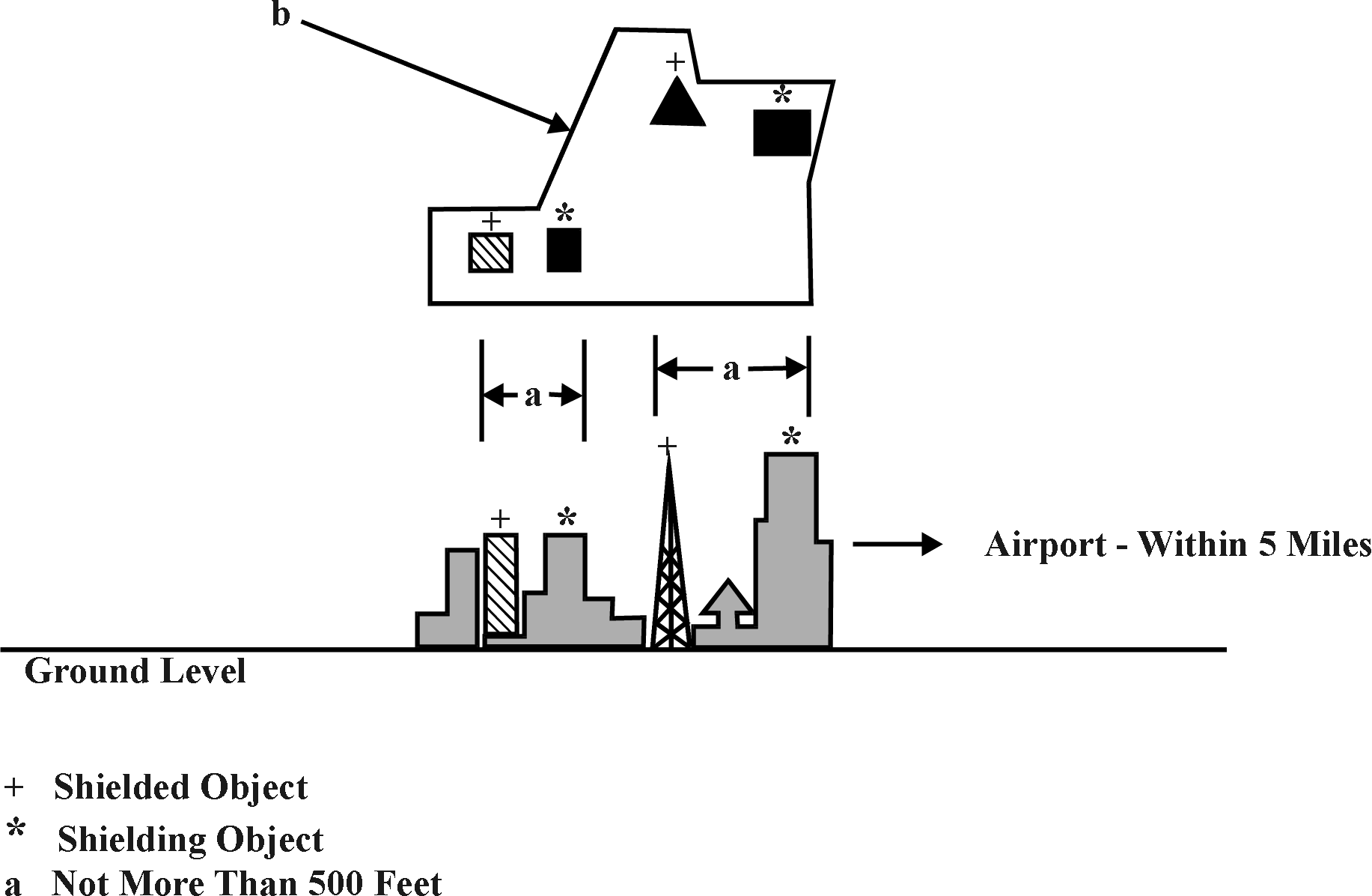
FIG 6-3-13
STANDARDS FOR DETERMINING SHIELDING
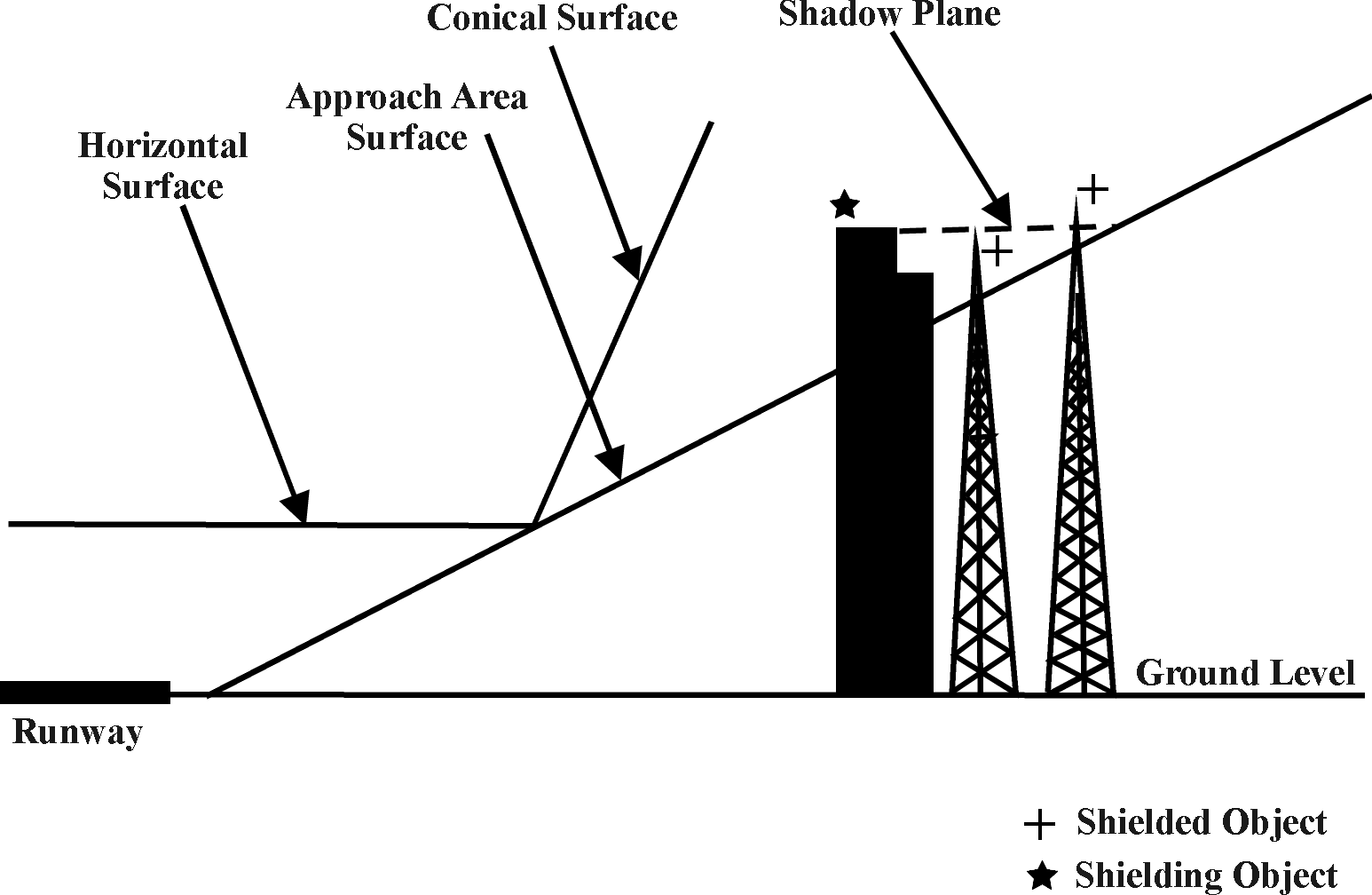
FIG 6-3-14
STANDARDS FOR DEVELOPING SHIELDING: PERSPECTIVE OF A SHADOW PLANE
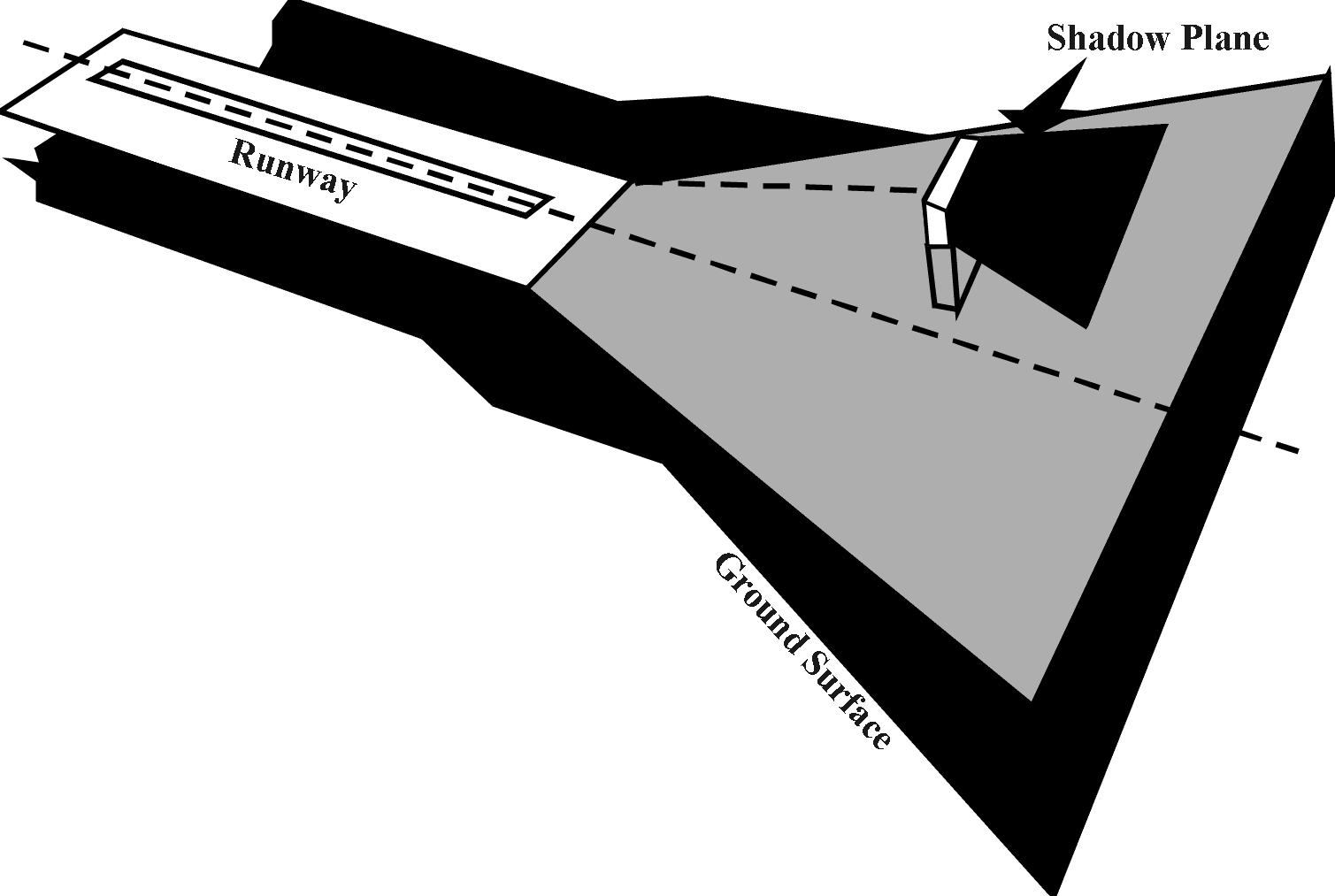
FIG 6-3-15
STANDARDS FOR DETERMINING SHIELDING: EXAMPLES OF SHADOW PLANES
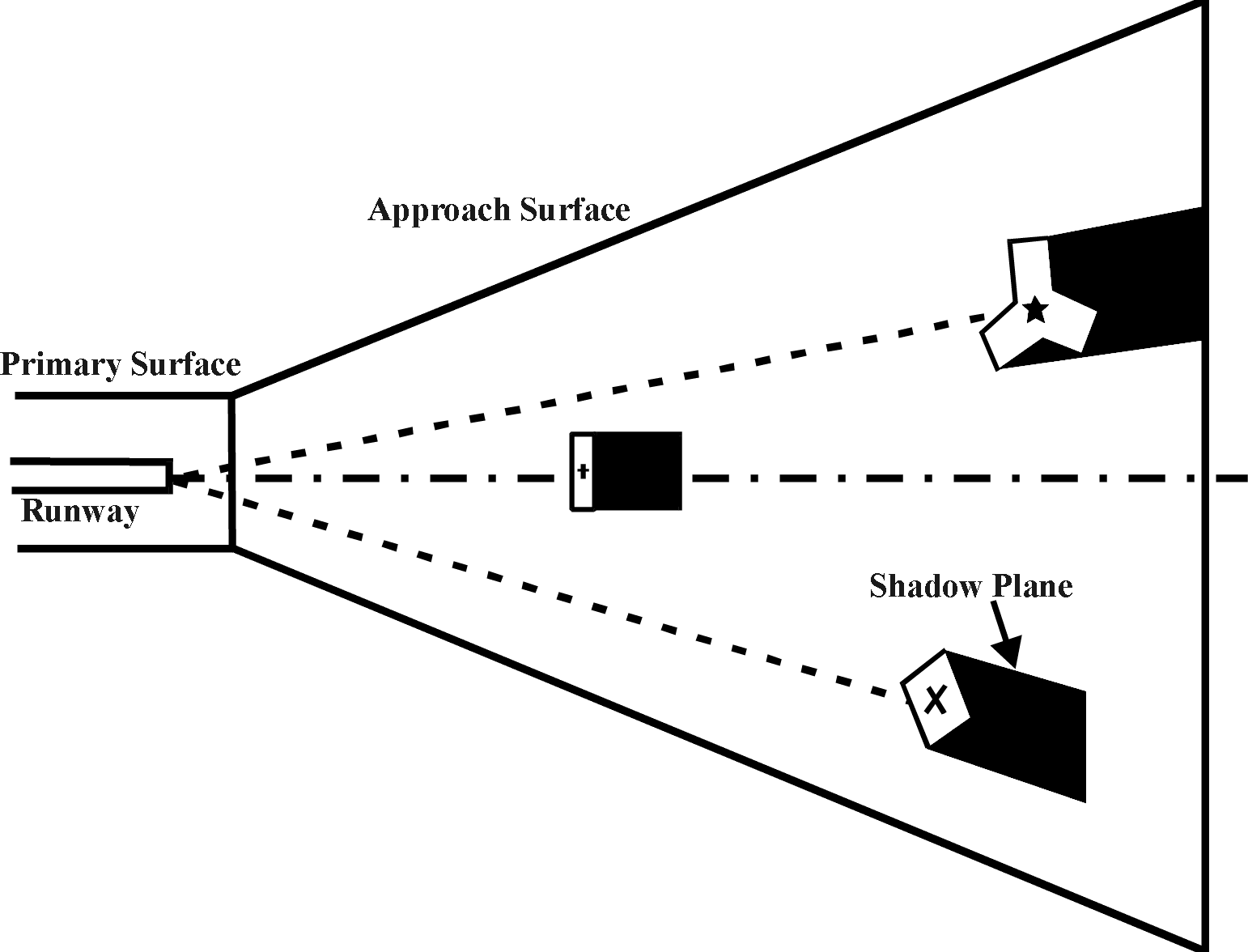
FIG 6-3-16
Frequency Protected Service Volume for ILS Front Course
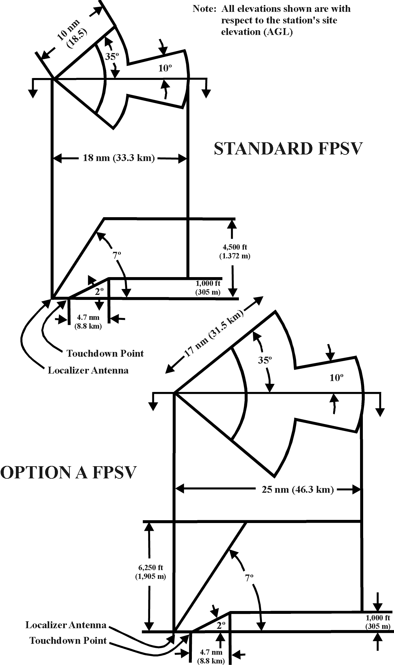
FIG 6-3-17
Frequency Protected Service Volume for ILS Back Course
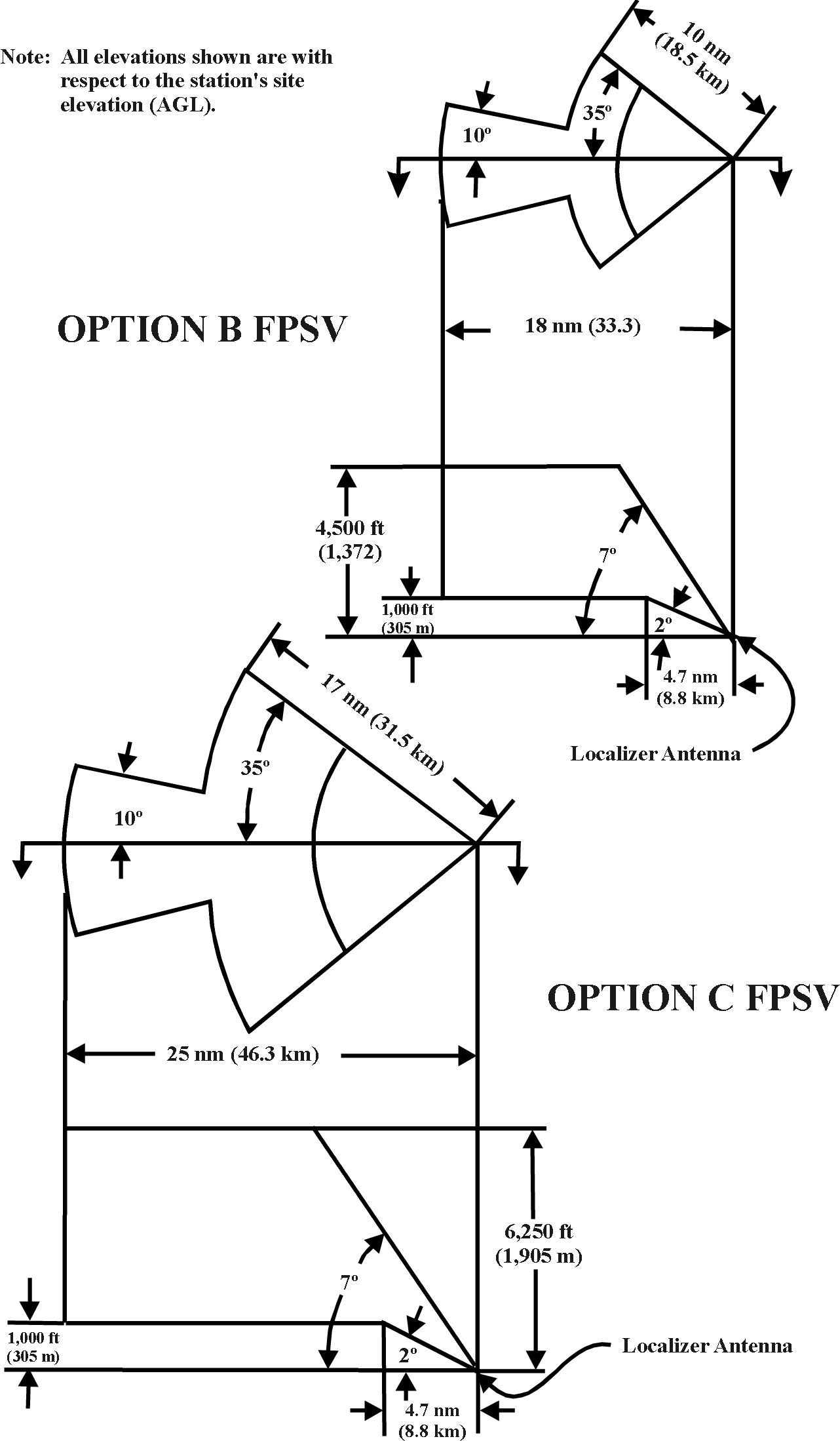
FIG 6-3-18
Frequency Protected Service Volume for VOR
|