ENR 1.16 Performance-Based Navigation (PBN) and Area Navigation (RNAV)
1.. General
- Introduction to PBN. As air travel has evolved, methods of navigation have improved to give operators more flexibility. PBN exists under the umbrella of area navigation (RNAV). The term RNAV in this context, as in procedure titles, just means “area navigation,” regardless of the equipment capability of the aircraft. (See FIG ENR 1.16-1.) Many operators have upgraded their systems to obtain the benefits of PBN. Within PBN there are two main categories of navigation methods or specifications: area navigation (RNAV) and required navigation performance (RNP). In this context, the term RNAV x means a specific navigation specification with a specified lateral accuracy value. For an aircraft to meet the requirements of PBN, a specified RNAV or RNP accuracy must be met 95 percent of the flight time. RNP is a PBN system that includes onboard performance monitoring and alerting capability (for example, Receiver Autonomous Integrity Monitoring (RAIM)). PBN also introduces the concept of navigation specifications (NavSpecs) which are a set of aircraft and aircrew requirements needed to support a navigation application within a defined airspace concept. For both RNP and RNAV NavSpecs, the numerical designation refers to the lateral navigation accuracy in nautical miles which is expected to be achieved at least 95 percent of the flight time by the population of aircraft operating within the airspace, route, or procedure. This information is detailed in International Civil Aviation Organization's (ICAO) Doc 9613, Performance-based Navigation (PBN) Manual and the latest FAA AC 90-105, Approval Guidance for RNP Operations and Barometric Vertical Navigation in the U.S. National Airspace System and in Remote and Oceanic Airspace.
FIG ENR 1.16-1Navigation Specifications 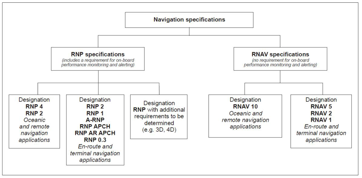
- Area Navigation (RNAV)
- General. RNAV is a method of navigation that permits aircraft operation on any desired flight path within the coverage of ground- or space-based navigation aids or within the limits of the capability of self-contained aids, or a combination of these. In the future, there will be an increased dependence on the use of RNAV in lieu of routes defined by ground-based navigation aids. RNAV routes and terminal procedures, including departure procedures (DPs) and standard terminal arrivals (STAR), are designed with RNAV systems in mind. There are several potential advantages of RNAV routes and procedures:
- Time and fuel savings;
- Reduced dependence on radar vectoring, altitude, and speed assignments allowing a reduction in required ATC radio transmissions; and
- More efficient use of airspace.
In addition to information found in this manual, guidance for domestic RNAV DPs, STARs, and routes may also be found in Advisory Circular 90-100, U.S. Terminal and En Route Area Navigation (RNAV) Operations.
- RNAV Operations. RNAV procedures, such as DPs and STARs, demand strict pilot awareness and maintenance of the procedure centerline. Pilots should possess a working knowledge of their aircraft navigation system to ensure RNAV procedures are flown in an appropriate manner. In addition, pilots should have an understanding of the various waypoint and leg types used in RNAV procedures; these are discussed in more detail below.
- Waypoints. A waypoint is a predetermined geographical position that is defined in terms of latitude/longitude coordinates. Waypoints may be a simple named point in space or associated with existing navaids, intersections, or fixes. A waypoint is most often used to indicate a change in direction, speed, or altitude along the desired path. RNAV procedures make use of both fly-over and fly-by waypoints.
- Fly-by waypoints. Fly-by waypoints are used when an aircraft should begin a turn to the next course prior to reaching the waypoint separating the two route segments. This is known as turn anticipation.
- Fly-over waypoints. Fly-over waypoints are used when the aircraft must fly over the point prior to starting a turn.
FIG ENR 1.16-2Fly-by and Fly-over Waypoints 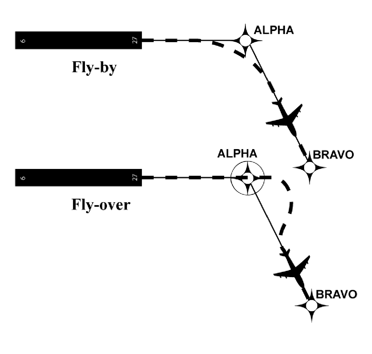
- RNAV Leg Types. A leg type describes the desired path proceeding, following, or between waypoints on an RNAV procedure. Leg types are identified by a two-letter code that describes the path (e.g., heading, course, track, etc.) and the termination point (e.g., the path terminates at an altitude, distance, fix, etc.). Leg types used for procedure design are included in the aircraft navigation database, but not normally provided on the procedure chart. The narrative depiction of the RNAV chart describes how a procedure is flown. The “path and terminator concept” defines that every leg of a procedure has a termination point and some kind of path into that termination point. Some of the available leg types are described below.
- Track to Fix. A Track to Fix (TF) leg is intercepted and acquired as the flight track to the following waypoint. Track to a Fix legs are sometimes called point-to-point legs for this reason. Narrative: “direct ALPHA, then on course to BRAVO WP.” See FIG ENR 1.16-3.
- Direct to Fix. A Direct to Fix (DF) leg is a path described by an aircraft's track from an initial area direct to the next waypoint. Narrative:“turn right direct BRAVO WP.” See FIG ENR 1.16-4.
FIG ENR 1.16-3Track to Fix Leg Type 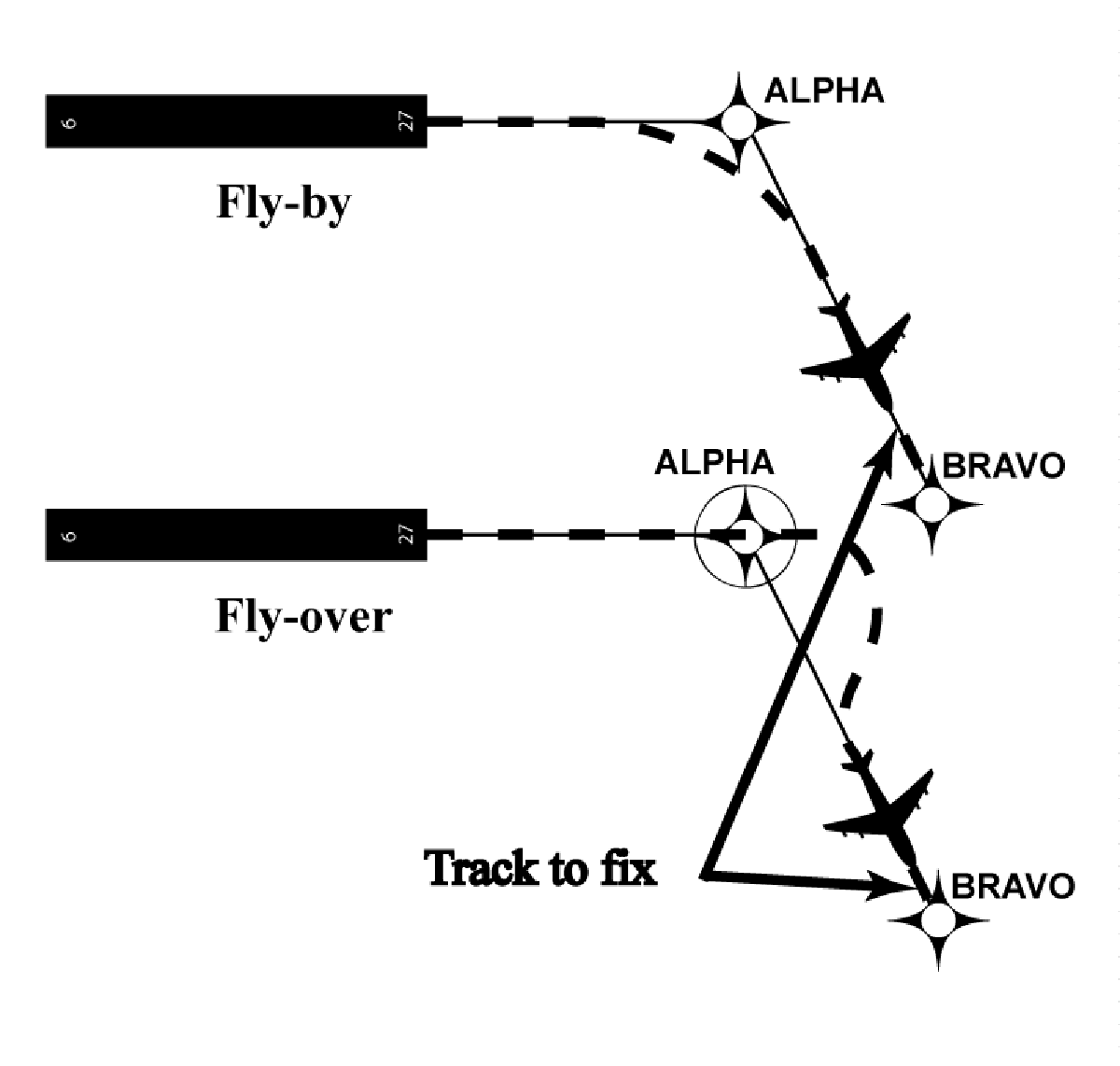
FIG ENR 1.16-4Direct to Fix Leg Type 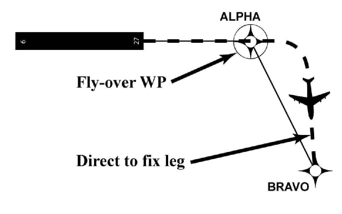
- Course to Fix. A Course to Fix (CF) leg is a path that terminates at a fix with a specified course at that fix. Narrative:“on course 150 to ALPHA WP.” See FIG ENR 1.16-5.
FIG ENR 1.16-5Course to Fix Leg Type 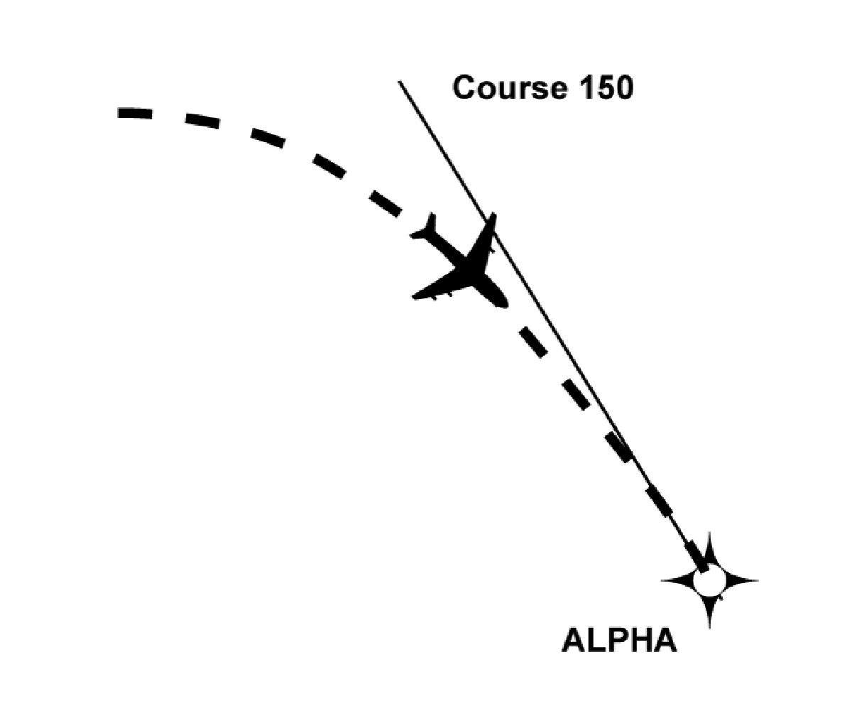
- Radius to Fix. A Radius to Fix (RF) leg is defined as a constant radius circular path around a defined turn center that terminates at a fix. See FIG ENR 1.16-6.
FIG ENR 1.16-6Radius to Fix Leg Type 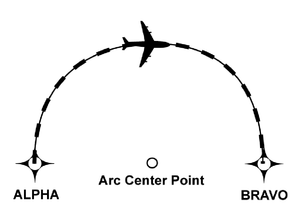
- Heading. A Heading leg may be defined as, but not limited to, a Heading to Altitude (VA), Heading to DME range (VD), and Heading to Manual Termination, i.e., Vector (VM). Narrative: “climb heading 350 to 1500”, “heading 265, at 9 DME west of PXR VORTAC, right turn heading 360”, “fly heading 090, expect radar vectors to DRYHT INT.”
- Navigation Issues. Pilots should be aware of their navigation system inputs, alerts, and annunciations in order to make better-informed decisions. In addition, the availability and suitability of particular sensors/systems should be considered.
- GPS/WAAS. Operators using TSO-C129(), TSO-C196(), TSO-C145() or TSO-C146() systems should ensure departure and arrival airports are entered to ensure proper RAIM availability and CDI sensitivity.
- DME/DME. Operators should be aware that DME/DME position updating is dependent on navigation system logic and DME facility proximity, availability, geometry, and signal masking.
- VOR/DME. Unique VOR characteristics may result in less accurate values from VOR/DME position updating than from GPS or DME/DME position updating.
- Inertial Navigation. Inertial reference units and inertial navigation systems are often coupled with other types of navigation inputs, e.g., DME/DME or GPS, to improve overall navigation system performance.
- Flight Management System (FMS). An FMS is an integrated suite of sensors, receivers, and computers, coupled with a navigation database. These systems generally provide performance and RNAV guidance to displays and automatic flight control systems.
- Inputs can be accepted from multiple sources such as GPS, DME, VOR, LOC and IRU. These inputs may be applied to a navigation solution one at a time or in combination. Some FMSs provide for the detection and isolation of faulty navigation information.
- When appropriate navigation signals are available, FMSs will normally rely on GPS and/or DME/DME (that is, the use of distance information from two or more DME stations) for position updates. Other inputs may also be incorporated based on FMS system architecture and navigation source geometry.
- RNAV Navigation Specifications (Nav Specs)
NavSpecs are a set of aircraft and aircrew requirements needed to support a navigation application within a defined airspace concept. For both RNP and RNAV designations, the numerical designation refers to the lateral navigation accuracy in nautical miles which is expected to be achieved at least 95 percent of the flight time by the population of aircraft operating within the airspace, route, or procedure. (See FIG ENR 1.16-1.)
- RNAV 1. Typically RNAV 1 is used for DPs and STARs and appears on the charts. Aircraft must maintain a total system error of not more than 1 NM for 95 percent of the total flight time.
- RNAV 2. Typically RNAV 2 is used for en route operations unless otherwise specified. T‐routes and Q‐routes are examples of this Nav Spec. Aircraft must maintain a total system error of not more than 2 NM for 95 percent of the total flight time.
- RNAV 10.Typically RNAV 10 is used in oceanic operations. See paragraph ENR 7.4 for specifics and explanation of the relationship between RNP 10 and RNAV 10 terminology.
- Waypoints. A waypoint is a predetermined geographical position that is defined in terms of latitude/longitude coordinates. Waypoints may be a simple named point in space or associated with existing navaids, intersections, or fixes. A waypoint is most often used to indicate a change in direction, speed, or altitude along the desired path. RNAV procedures make use of both fly-over and fly-by waypoints.
- General. RNAV is a method of navigation that permits aircraft operation on any desired flight path within the coverage of ground- or space-based navigation aids or within the limits of the capability of self-contained aids, or a combination of these. In the future, there will be an increased dependence on the use of RNAV in lieu of routes defined by ground-based navigation aids. RNAV routes and terminal procedures, including departure procedures (DPs) and standard terminal arrivals (STAR), are designed with RNAV systems in mind. There are several potential advantages of RNAV routes and procedures:
2.. Required Navigation Performance (RNP)
3.. Use of Suitable Area Navigation (RNAV) Systems on Conventional Procedures and Routes
4.. Recognizing, Mitigating and Adapting to GNSS Jamming and/or Spoofing
- The low-strength data transmission signals from GNSSsatellites are vulnerable to various anomalies that can significantly reduce the reliability of the navigation signal. The GPS signal is vulnerable and has many uses in aviation (e.g., communication, navigation, surveillance, safety systems and automation); therefore, pilots must place additional emphasis on closely monitoring aircraft equipment performance for any anomalies and promptly inform Air Traffic Control (ATC) of any apparentGPS degradation. Pilots should also be prepared to operate without GNSS navigation systems.
- GNSSsignals are vulnerable to intentional and unintentional interference from a wide variety of sources, including radars, microwave links, ionosphere effects, solar activity, multi-path error, satellite communications GNSSrepeaters, and even some systems onboard the aircraft. In general, these types of unintentional interference are localized and intermittent. Of greater and growing concern is the intentional and unauthorized interference of GNSSsignals by persons using “jammers” or “spoofers” to disrupt air navigation by interfering with the reception of valid satellite signals.
- Manufacturers, operators, and air traffic controllers should be aware of the general impacts of GNSS jamming and/or spoofing which include, but are not limited to:
- Inability to use GNSS for navigation.
- Inability to use hybrid GNSS inertial systems for navigation.
- Loss of, or degraded, performance-based navigation (PBN) capability (e.g., inability to fly required navigation performance (RNP) procedures).
- Unreliable triggering of Terrain Awareness and Warning Systems (TAWS).
- Inaccurate aircraft position on navigation display (e.g., moving map and electronic flight bag).
- Loss of, or erroneous, Automatic Dependent Surveillance-Broadcast (ADS-B) outputs.
- Unexpected effects when navigating with conventional NAVAIDS (e.g., if the aircraft is spoofed from the intended flight path, autotuning will not select the nearby NAVAID).
- Unanticipated position-dependent flight management system effects (e.g., erroneous insufficient fuel indication).
- Failure or degradation of Air Traffic Management (ATM) infrastructure and its associated systems reliant on GNSS, resulting in potential airspace infringements and/or route deviations.
- Failure of, or erroneous aircraft clocks (resulting in inability to log on to Controller-Pilot Data Link Communications (CPDLC).
- Erroneous wind and ground speed indications.
- When flying IFR, pilots should have additional navigation equipment for their intended route to crosscheck their position. Routine checks of position against VOR or DMEinformation, for example, could help detect a compromised GNSSsignal. Pilots transitioning to VOR navigation in response toGNSSanomalies should refer to the Chart Supplement U.S. to identify airports with available conventional approaches associated with the VOR Minimum Operational Network (MON) program. (Reference Aeronautical Information Publication AIP ENR 4.1-2.6.3).
- Prior to departure, the FAA recommends operators to:
- Be aware of potential risk locations.
- Check for any relevant Notices to Airmen (NOTAMs).
- Plan fuel contingencies.
- Plan to use conventional NAVAIDs and appropriate arrival/approach procedures at the destination.
- Follow the detailed guidance from the respective Original Equipment Manufacturer (OEM).
- During flight, the FAA recommends operators do the following:
- Be vigilant for any indication that the aircraft's GNSS is disrupted by reviewing the manufacturer's guidance for that specific aircraft type and avionics equipage. Verify the aircraft position by means of conventional NAVAIDs, when available. Indications of jamming and/or spoofing may include:
- Changes in actual navigation performance.
- Aircraft clock changes (e.g., incorrect time).
- Incorrect Flight Management System (FMS) position.
- Large shift in displayed GNSS position.
- Primary Flight Display (PFD)/Navigation Display (ND) warnings about position error.
- Other aircraft reporting clock issues, position errors, or requesting vectors.
- Assess operational risks and limitations linked to the loss of GNSS capability, including any on-board systems requiring inputs from a GNSS signal.
- Ensure NAVAIDs critical to the operation for the intended route/approach are available.
- Remain prepared to revert to conventional instrument flight procedures.
- Promptly notify ATC if they experience GNSSanomalies. Pilots should NOT normally inform ATC of GNSS jamming and/or spoofing when flying through a knownNOTAMed testing area, unless they require ATC assistance. (See AIP ENR 4.1-22.)
- Be vigilant for any indication that the aircraft's GNSS is disrupted by reviewing the manufacturer's guidance for that specific aircraft type and avionics equipage. Verify the aircraft position by means of conventional NAVAIDs, when available. Indications of jamming and/or spoofing may include:
- Post flight, the FAA recommends operators to:
- Document any GNSS jamming and/or spoofing in the maintenance log to ensure all faults are cleared.
- File a detailed report at the reporting site: Report a GPS Anomaly Federal Aviation Administration,
www.faa.gov/air_traffic/nas/gps_reports.