Chapter 10. Basic
Section 3. Airport Standards
10-3-1. DESIGN STANDARDS
- For Federally obligated airports, it is the responsibility of the airport proponent/sponsor/planner to comply with FAA airport design standards.
- For non-Federally obligated airports or National Plan of Integrated Airport Systems (NPIAS) airports, it should be encouraged that the airport proponent/sponsor/planner comply with FAA airport design standards.
- It should be noted when airport design standards are combined with appropriate state and local zoning ordinances, the resultant effect should:
- Assure the lowest possible operational altitudes for aircraft;
- Protect the economic investment in the airport; and
- Promote safety in the areas affected by the airport by assuring, through proper development, compatible land use.
10-3-2. AIRPORT SPACING GUIDELINES AND TRAFFIC PATTERN AIRSPACE AREAS
- The following guidelines are to be used as aids when evaluating airport proposals. The guidelines may also be used to determine airspace requirements to accommodate a given operation under a given condition, areas of potential air traffic conflict for aircraft having certain operational and performance characteristics, and the degree of aircraft operational flight compatibility with other airports in a given area. These guidelines are not to be construed as authorizations for aircraft operations contrary to any Code of Federal Regulations, nor are the dimensions to be construed as air traffic separation standards.
- Aircraft Approach Categories - The factor used to categorize the following aircraft was taken from part 97. This factor is based on 1.3 times the stall speed with aircraft in landing configuration at maximum certificate landing weight.
- Category A - Speed less than 91 knots. This category includes civil single-engine aircraft, light twins, and some of the heavier twins.
- Category B - Speed 91 knots or greater but less than 121 knots.
- Category C - Speed 121 knots or greater but less than 141 knots.
- Category D - Speed 141 knots or greater but less than 166 knots.
- Category E - Speed 166 knots or greater. This category includes, for the most part, those military, experimental, and some civil aircraft having extremely high speeds and critical performance characteristics.
- IFR Radar Airspace.
- Air traffic control airspace requirements for a specific runway or airport are generally dictated by the approach category of the aircraft that will use the airport and the direction of the associated instrument approaches and departures. Based on these factors, the following rectangular airspace areas were developed as general guides for the planning or siting of new airports and the designation of instrument runways when IFR radar control procedures are contemplated or programmed for a single airport operation, or under certain conditions, multiple airport operations. No provisions are made for holding or for procedure turns within the airspace areas.
- Airports that are regularly used by Category C aircraft or larger: 10 miles in the departure direction, 15 miles in the direction from which approaches will be made, and 5 miles either side of the extended runway centerline.
- Airports which are regularly used by Category B and smaller aircraft: 5 miles in the departure direction, 10 miles in the direction from which approaches will be made, and 4 miles either side of the extended runway centerline.
- In metropolitan areas requiring more than one airport: the primary instrument runways at all airports should be aligned in the same general direction to allow maximum spacing between airspace areas.
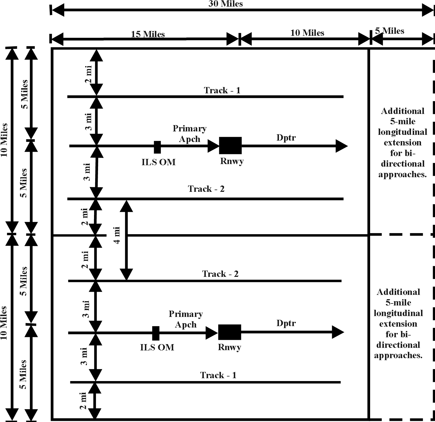
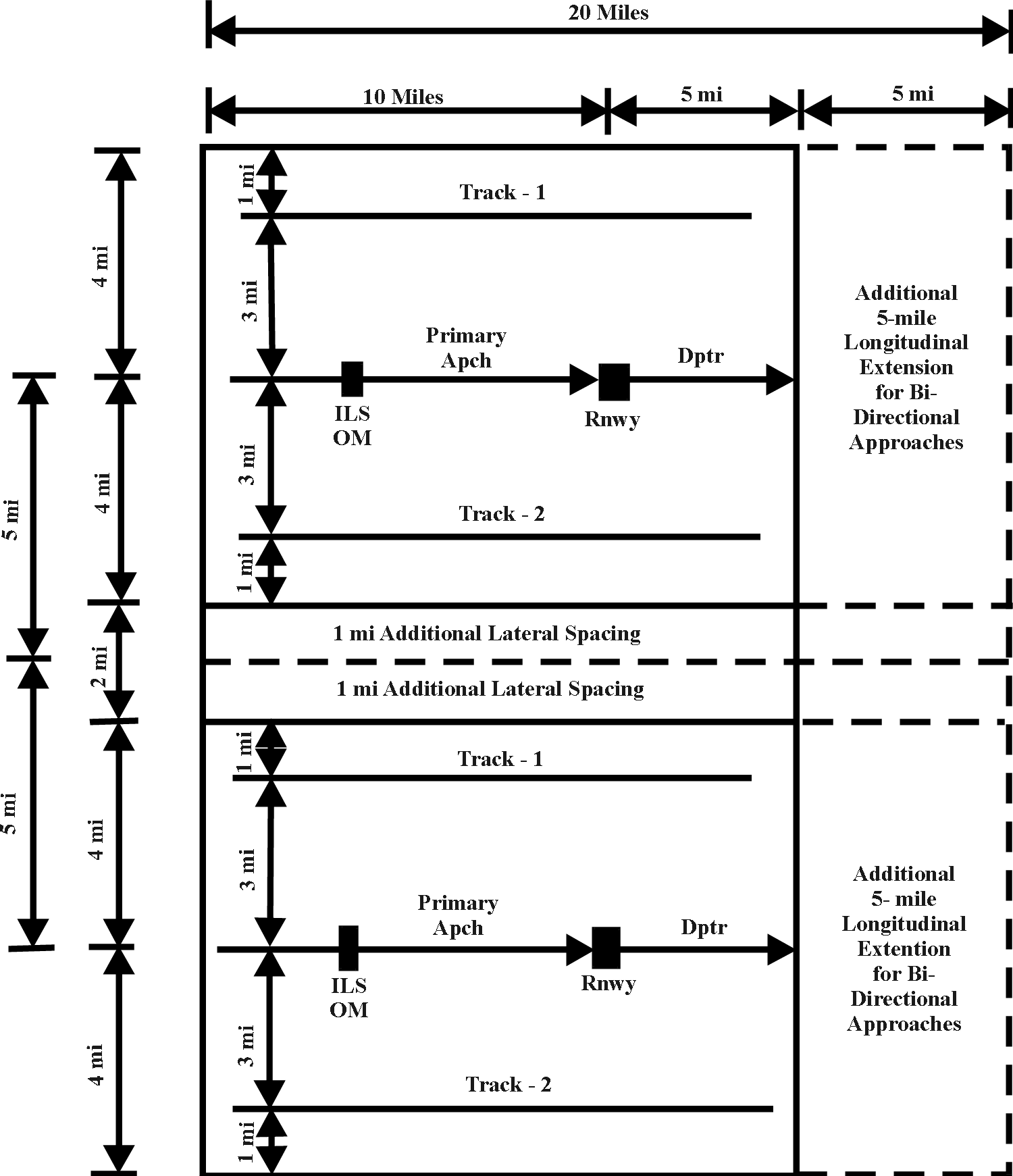
- At airports having parallel approaches: the rectangular airspace areas should be applied to each runway. Should the instrument runways at an airport have bi-directional instrument approach capabilities, the total length of the larger airspace areas should be increased to 30 miles for Category C and D aircraft, and to 20 miles for Category A and B aircraft in the smaller airspace areas.
- These airspace dimensions will not, nor are they intended to, contain sufficient airspace to provide for completely independent IFR operations. Normally, these areas will provide for reasonable operational efficiency if the traffic pattern airspace areas of adjacent airports do not overlap. However, in large metropolitan areas where there is an extremely heavy mix of en route and terminal traffic, reasonable operational efficiency may not result even though the airspace areas do not overlap. Such situations require a thorough review of the procedural potential of the area, as well as alternate site considerations. In conducting studies where complete radar environments call for the larger airspace areas, and such areas abut each other but do not overlap, there is adequate space for:
- Approach and departure on the runway centerline.
- Two additional tracks offset from and parallel to the runway centerline. A minimum of four miles is provided between adjacent tracks of different areas (see FIG 10-3-1).
- Where two smaller areas are adjacent but do not overlap, an additional 1-mile spacing is required on two of the longitudinal sides (see FIG 10-3-2).
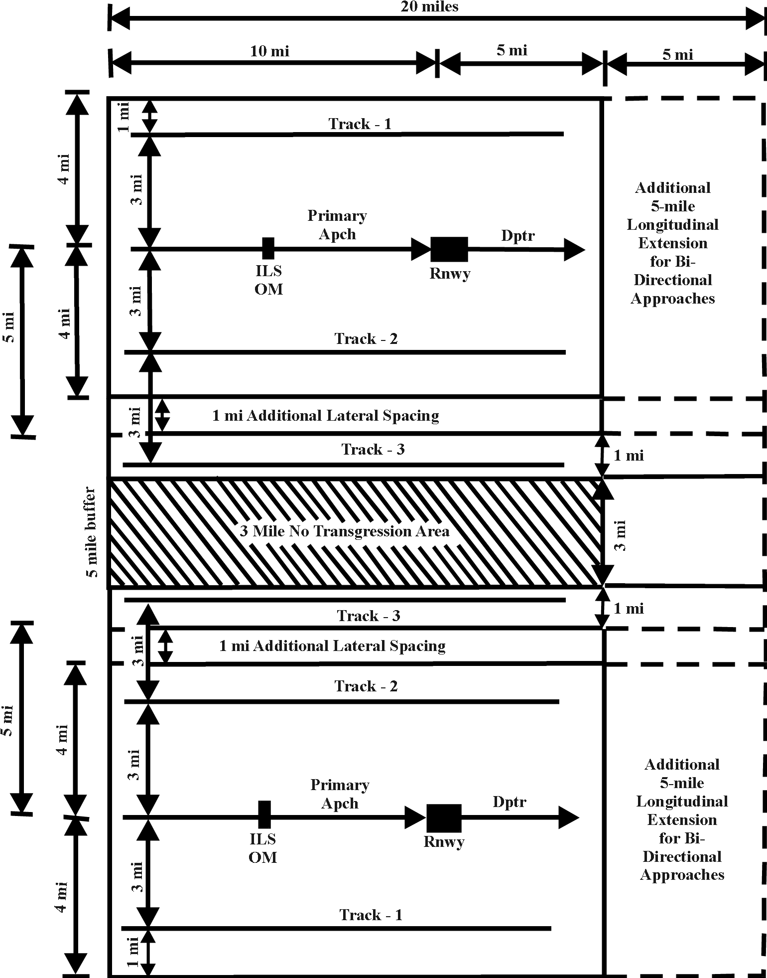
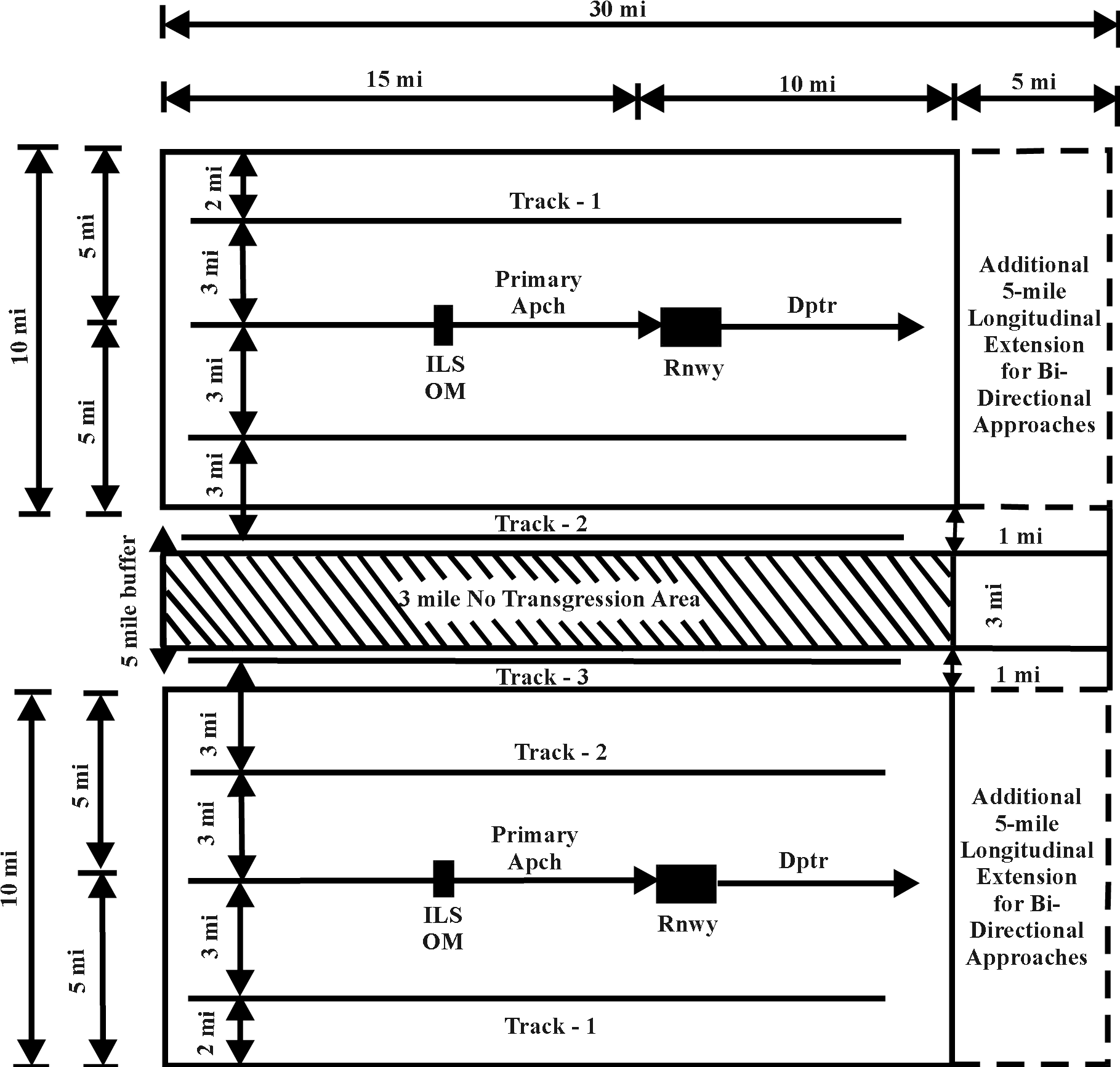
- When the anticipated traffic volume at an existing or proposed airport requires additional airspace for greater airspace-use efficiency and operational flexibility, expand the airspace, where available, by providing a 5-mile buffer area between the adjacent airports involved. This additional airspace will provide two additional tracks offset from and parallel to the runway centerlines within the airspace areas of the adjacent airports and one additional track for each airport within the 5-mile buffer area. A minimum of 3 miles is provided between each track paralleling the runway centerline and each additional track in the buffer area. A 3-mile no transgression area is also provided between the two airports (see FIG 10-3-3).
- If additional airspace is required in the smaller areas for greater airspace-use efficiency and flexible operation, the procedures for determining the additional airspace are identical to those used for the larger areas, except that the smaller airspace should be used in lieu of the larger airspace areas. The 1-mile additional spacing should also be applied, as outlined in subparagraph b.3. above, in addition to the 5-mile buffer area, as outlined in subparagraph b.4. above (see FIG 10-3-4).
- Air traffic control airspace requirements for a specific runway or airport are generally dictated by the approach category of the aircraft that will use the airport and the direction of the associated instrument approaches and departures. Based on these factors, the following rectangular airspace areas were developed as general guides for the planning or siting of new airports and the designation of instrument runways when IFR radar control procedures are contemplated or programmed for a single airport operation, or under certain conditions, multiple airport operations. No provisions are made for holding or for procedure turns within the airspace areas.
- IFR Nonradar Airspace - A wide range of procedures is available for airspace requirements associated with instrument approach procedures at IFR airports without radar services. Therefore, no attempt has been made to describe these requirements in detail. However, should it become necessary to determine the airspace requirements at such airports, apply the appropriate primary airspace areas and “aircraft approach categories" discussed in subparagraph a. above. Additional information is contained in AC 150/5300-13, Airport Design.
- VFR Airspace - A primary objective in an airport/airspace study is to determine whether compatible VFR traffic patterns may be developed for a new airport or when to alter a runway layout at an existing airport located in proximity to other airports. Because flight tracks and climb/descent profiles vary when operating in a VFR traffic pattern, the following guidelines are offered for use in these studies:
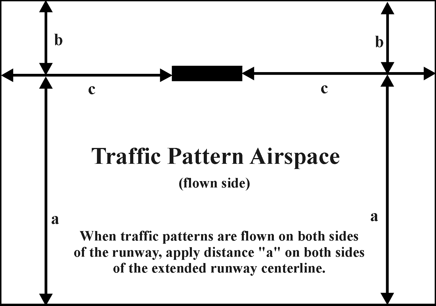
- Traffic pattern airspace (see paragraph 6-3-8) of one airport may touch but should not overlap the traffic pattern airspace of another airport;
- Traffic pattern airspace should be enlarged as described in paragraph 6-3-11 when more than four aircraft of the same category operate in a VFR traffic pattern at the same time.
10-3-3. DESIGNATION OF INSTRUMENT RUNWAYS, CHANGES OF AIRPORT STATUS VFR TO IFR AND LOWERING MINIMUMS
Requests for designation of instrument runways, which relate to installation or qualification for precision landing aids, and proposals for a change in airport status from VFR to IFR, or lowering instrument approach minimums usually take one of the following forms:
- In cases involving Federally obligated airports, the Airports Division must be responsible for coordinating, corresponding directly with the proponents, and formulating the official determination.
- In cases requesting an instrument procedure not involving a Federally obligated airport, the FPT must coordinate directly with the proponent.
- In cases requesting the installation of a NAVAID not involving a Federally obligated airport, the Technical Operations Services area office is responsible for coordinating, corresponding directly with the proponent, and formulating the official determination.
- A proposal submitted under part 157 (FAA Form 7480-1) not involving a request for an instrument procedure or an installation of a NAVAID, the appropriate Airports Division must be responsible for coordinating, corresponding directly with the proponent, and formulating the official determination, regardless of which division receives the proposal.
- A change to the Airport Layout Plan (ALP). The Flight Procedures Team must be responsible for coordinating the requests for instrument procedures not involving a Federally obligated airport. Coordination of requests for installation of NAVAIDs must be in accordance with Part 4 of this Order. The Airports Office must be responsible for coordinating submittals under part 157 and all other construction on a public-use airport, and changes to approved ALPs. Designation of instrument runways on all Federally obligated airports must be the responsibility of the Airports Division and will be treated in the same manner as a revision to the ALP. Regardless of where the coordination begins, air traffic, Technical Operations Services, Flight Standards, Airports, and Flight Procedures Team must have an opportunity to review and comment on the proposal. No division/service area office must require dual reporting of such a proposal. The responsible coordinating division/service area office must correspond directly with the proponent and formulate the official determination.
10-3-4. AIRSPACE FEASIBILITY STUDY
Before expending funds for acquisition of real property, development of the ALP, or plans and specifications for new airports and major airfield improvements, feasibility studies or preliminary airport site analyses are encouraged. Normally, preliminary airport site analyses are made on all Federal agreement projects involving airport site selections. Analyses of this nature allow the agency to evaluate the proposals and advise the proponents as to their feasibility from a safety and airspace use standpoint in addition to other related matters. Guidance for conducting these airport studies is contained in AC 150/5070-6A, Airport Master Plans. That AC describes the major considerations when selecting a site for a new airport for which Federal aid is anticipated. Airport studies of this nature are coordinated in the same manner as Federal agreement proposals, except that the proposals are not circularized to the public unless specifically requested by the proponent.
10-3-5. ONSITE EVALUATION
The intent of the FAA is to achieve safe airport operations and to fulfill its responsibilities of assuring that unsafe conditions will not exist. Therefore, if there is an indication of unsafe conditions or information to evaluate the proposal cannot be obtained from the proponent, an onsite evaluation of the proposal must be considered before issuing a determination. Such an evaluation may be necessary if the proposal would be located in a congested area or the study indicates the presence of obstructions that may affect the safe and efficient use of the airspace. An onsite evaluation may also be necessary if information pertaining to the proposal is insufficient for arriving at a determination. Airports, air traffic, Flight Procedures Team, Technical Operations Services, and Flight Standards personnel must assist in the evaluation as necessitated by the situation requiring evaluation.
10-3-6. FORMULATION OF FAA DETERMINATION
The FAA determination must be a composite of the airspace review and the comments and findings received from other interested FAA offices. Should there be a disagreement in the airspace findings or between other comments received, the disagreement must be resolved before formulating the FAA determination.