Chapter 5. Aerial Refueling
Section 2. Track Requirements
5-2-1. DESCRIPTION
- Aerial refueling tracks are established to accommodate refueling operations along a prescribed route. An aerial refueling track consists of an ARIP, ARCP, and an exit point. Navigation check points between the ARCP and exit point are specified, as required, to facilitate navigation along the route. It also includes the tanker orbit pattern at the ARCP, and the altitude block(s) assigned for the track.
- Instructions for preparing and submitting track proposals are contained in Section 4 of this chapter.
5-2-2. NAVIGATION ALONG AIR REFUELING TRACK
Navigation along an aerial refueling track must be accomplished using a combination of airborne equipment and NAVAIDs as appropriate.
5-2-3. ARIP ESTABLISHMENTS
The ARIP must be established:
- At a distance from the ARCP which must meet the requirements of the primary user command.
- Within 30 degrees either side of the extended centerline of the track on which the actual aerial refueling operation is to be accomplished.
- Within the same ARTCC/CCF/HCF area as the ARCP whenever practical.
- So as to provide for a direct course between the ARIP and ARCP.
5-2-4. DEGREE*DISTANCE TRACK DEFINITION
- Tracks predicated on degree-distance track definition must provide:
- A means of navigation from the ARIP to the exit point via a usable NAVAID radial/distance or along offshore extended routes.
- A means of navigation from at least one navigational checkpoint or from the exit point to proceed IFR en route via a usable NAVAID.
- Tracks located over water or in remote areas or beyond the range of fixed NAVAIDs must be predicated on geographical coordinate route definition with suitable navigation means provided by the user command.
5-2-5. TANKER ORBIT PATTERNS
The following describes typical orbit patterns for jet aircraft and turboprop/conventional type aircraft.
- Turbojet - Normally, a rectangle 60 NM long (48 NM uptrack and 12 NM downtrack from ARCP or anchor point) and 25 NM wide, oriented longitudinally along the ARIP-ARCP or anchor point segment of the track so as to provide 7 NM of airspace on the non-holding side of the refueling track and 18 NM of airspace on the holding side. This pattern will normally be designed for left turns. When right turns are used, the orientation of the orbit pattern will shift accordingly. (See FIG 5-2-1, Components of a Typical Turbojet Aerial Refueling Track.)
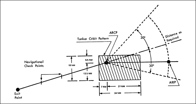
- Turboprop - Normally, a rectangle 34 NM long (27 NM uptrack and 7 NM downtrack from ARCP or anchor point) and 18 NM wide, oriented longitudinally along the ARIP-ARCP or anchor point segment of the track so as to provide 4.5 NM of airspace on the non-holding side of the refueling track and13.5 NM of airspace on the holding side. The pattern will normally be designed for left turns. When right turns are used, the orientation of the orbit pattern will shift accordingly. (See FIG 5-2-2, Components of a Typical Turboprop Aerial Refueling Track.)
FIG 5-2-1Components of a Typical Turbojet Aerial Refueling Track 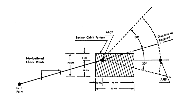
FIG 5-2-2Components of a Typical Turboprop Aerial Refueling Track