
Fokker F27 Mk 050
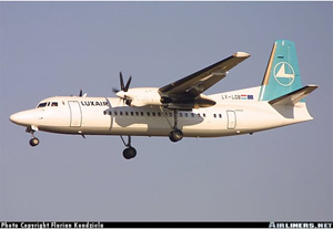
Photo copyright Florian Kondziela - used with permission
Luxair Flight LG9642/LH2420, LX-LGB
Luxembourg, Luxembourg
November 6, 2002
On November 6, 2002, a Fokker F27 Mk 050 turboprop-powered airplane, owned and operated by Luxair and registered as LX-LGB, departed Berlin as Flight LG 9642/LH 2420 to Luxembourg. Inadequate landing visibility was reported at the destination airport and remained throughout the approach. The crew attempted an approach, but visibility remained inadequate, and a go-around was initiated. Shortly after initiation of the go-around, ATC reported that visibility had improved to above the required minimums. The captain aborted the go-around and attempted to capture the glide slope from above. In attempting to capture the glide slope, the captain moved the power levers below the flight idle detent. Moving the power levers below the flight idle detent in flight was specifically prohibited by the Airplane Flight Manual. Upon landing gear extension, a design defect momentarily released the secondary mechanical low pitch stops and allowed the propellers on both engines to transit into the reverse pitch (beta) range.
The captain recognized that reverse pitch had been attained and moved the power levers back into the forward thrust region. However, the pitch on the right propeller continued to reduce and eventually went fully into reverse. In response to the effects of increased drag, loss of lift, and thrust asymmetry, the captain chose to shut down both engines in an attempt to maintain control. After shutdown, the left propeller feathered, but the right propeller remained in full reverse.
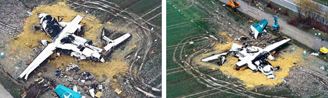
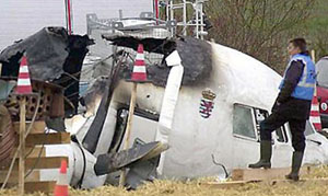
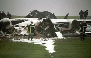
The airplane touched down near the edge of a highway 3.5 km short of the runway, bounced over the highway, broke up, and caught fire. Of the 19 passengers and three crew members on board, only the captain and one passenger survived.
History of Flight
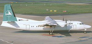
A Fokker F27 Mk 050, registered as LX-LGB and operated by Luxair, left Berlin for Luxembourg on Flight LG 9642/LH 2420 with 19 passengers and three crew members (captain, first officer and flight attendant) on board. Initial cruising altitude was flight level (FL) 180 - 18,000 feet. While en route the crew checked the destination weather and learned that the visibility was 100 meters with a runway visual range (RVR) of 250 meters in fog. The flight crew discussed the possibility of delays, and whether they would enter a holding pattern at the destination or divert to an alternate airport. No decision regarding the approach was made at the time, but no approach briefing was conducted in preparation for an approach.
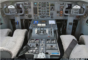
Photo copyright Jonathan Rankin - used with permission
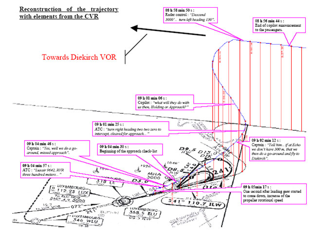
On initial contact with Luxembourg approach, the flight was instructed to enter the FL90 (9,000 feet) holding pattern at Diekirch VOR, and to expect radar vectors later for an instrument landing system (ILS) Category II approach to Runway 24 (A 4,000 meter long runway at an elevation of 1,214 feet and oriented on a heading of 241°).
During the initial stages of the approach, the pilot and copilot discussed concerns regarding the expectation that they would be instructed to hold and the amount of fuel they had available before a diversion to an alternate airport would be necessary. As the flight neared the point where it would enter the holding pattern, the controller cleared the flight to initiate an approach rather than enter the hold. The investigation concluded that this was an attempt by the controller to maintain separation between all aircraft in the hold at the time, and alleviated the need to assign a new and separate holding altitude for the accident flight.

View Larger
The flight crew was instructed to contact the tower approximately simultaneously with interception of the ILS beam (localizer and glideslope). The crew contacted the tower and reported that they were established on the localizer and were continuing the approach. Following this initial contact, a discussion between the tower and flight centered on the necessity for a visibility (RVR) of 300 meters to continue the approach and land.
RVR is measured from an automated instrument known as a transmissometer, which is located to the side of the runway. The transmissometer measures the maximum distance (in feet or meters) at which the runway lights or surface markings can be seen before they are lost in the fog or rain. Thus, it will be certain that on landing a pilot's visual range will be at least that reported distance (horizontal visibility) as the airplane rolls down the runway.
Some airports have only one transmissometer, placed near the touchdown (or initial) area of the runway. There might be another located at the midpoint (intermediate) section of the runway and/or at the far end (stopping end or rollout area). The tower issues the current RVR reading(s) and the pilot must determine if that visibility is at least the value required by his approach chart. If so, he may continue the approach and land. For example, if the pilot's approach chart requires 300 meters (1,000 feet) RVR, and the tower says the RVR is 250 meters (800 feet), then the flight crew must either wait for the visibility to improve or fly to their alternate airport. However, even if the RVR is measuring the legal visibility to begin the approach, when the airplane reaches the minimum descent altitude the pilot must still acquire visual contact with the approach lights in order to land. If the pilot does not have visual contact with the lights, a climb (go-around) must be initiated for the purpose of either executing another approach or fly to the alternate airport.
At 09:03:18, approximately two minutes before the crash, the tower controller transmitted: "9642 copied... uh, so continue approach and I'll keep you advised we didn't have 300 uh... uh during the last time."
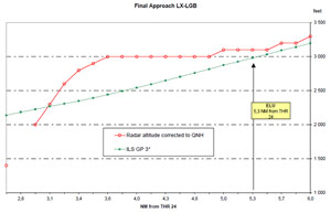
At 09:04:36, The tower controller informed another flight, "We have now on the three positions 275 meters." This message was heard by the crew of Luxair 9642 as they passed overhead ELU, maintaining 3,000ft. ELU was a decision point by which the flight should have either intercepted the glideslope or initiated a go-around.
At 09:04:46, the captain then announced to the copilot: "Yes, well we do a go-around, missed approach."
At this point, investigators concluded that the captain initiated a missed approach by advancing the power levers.
At 09:04:57, the tower controller transmitted an RVR to the crew, "Luxair 9642 RVR 300 meters 275 meters stop end 275 meters."
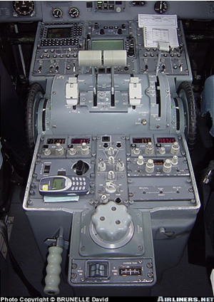
Photo copyright Brunelle David - used with permission
At 09:05:00 the Cockpit Voice Recorder (CVR) sounds indicated a variation in the rotation speed of the turbines, and the primary lock (i.e. ground range selector, which allows the power levers to be moved into the reverse pitch range) was lifted/removed. The Flight Data Recorder (FDR) indicated the start of engine power reduction.
The RVR value provided at 09:04:57, about 11 seconds after the captain said he would perform a "missed approach," corresponded exactly to the required landing minima. Investigators believed that this information triggered a sudden reversal of the captain's decision, and he resumed the approach without announcing that he was doing so. No procedure existed to capture the glide slope from above after having passed the final approach point.
The airplane performance aspects of a long landing are described in the following animation below. (Landing Performance Animation)
The captain brought the power levers to flight idle, and at the same time pulled the ground range selectors in order to be able to bring the power levers slightly further backwards. This action was deduced by the investigators, based on the values of the left and right high pressure turbine RPM parameters, which were below the flight idle minimum, and by the identified relevant noises on the CVR. The "secondary stop" installed on the engines maintained the power levers in a position slightly below the flight idle. The investigation concluded that the pilot's actions to reduce the power levers to a slightly lower position than the flight idle position was an attempt to increase the descent rate without accelerating, while intercepting the glide slope. Post accident investigation showed that it actually did not improve the deceleration.
At 09:05:05 the copilot responded to the tower controller, "9642 Roger so we continue," indicating that they would be continuing the approach.
At 09:05:08 the tower controller cleared Flight 9642 for landing.
At 09:05:13 the copilot acknowledged the landing clearance. This was the last communication with ATC.
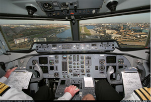
Photo copyright Serge Bailleui - used with permission
At 09:05:16 the FDR indicated the extension of the landing gear. At this point the FDR also indicated a heading of 238°, an indicated airspeed of 145 knots, and an altitude of 2,635 feet. Propeller torques (left and right) were 0% and 0 %. Propeller speeds (left and right) were 85% and 85%.
At 09:05:17 CVR sounds indicated an increase of rotational speed of at least one propeller and then numerous noises of selections, and power variations were recorded. The FDR indicated that the left propeller "blade angle" parameter switched from "normal" to "low pitch," signaling a propeller blade angle setting of less than 10°. The investigation concluded that the change in blade pitch from normal to low pitch was the result of the removal of the secondary blade low pitch stop, which had previously prevented the blade angle transit, even though the power levers were in a range where low pitch was commanded.
Post accident investigation demonstrated that the most probable cause for the removal of the secondary stop was the extension of the landing gear, which triggered the energizing of the flight idle stop solenoid relay due to a known design flaw in the antiskid control box. The investigation concluded that with all the mechanical locks having been removed, the captain continued to apply hand pressure on the power levers, and may have unintentionally moved them further backwards without realizing that he was now in beta mode, having passed through the ground idle position towards full reverse.
View Larger
At 09:05:18 the FDR indicated the right hand propeller "blade angle" parameter switched from "normal" to "low pitch."
At 09:05:19 the captain says, "What's that?" CVR sounds indicated throttle going to, or through, the ground idle position. Reverse power was applied to both engines, which was documented by a rapid increase of all engine parameters. The power levers were then set beyond the flight idle position back into the flight range.
At 09:05:20 the FDR indicated the start of flap retraction. Two seconds later, both propeller speeds had increased, and the left engine was shut down.
At 09:05:23 the left propeller RPM drops below 50% and the left engine generator is taken offline by the generator control unit (GCU). As a result, the right engine generator subsequently powered all electrical buses.
At 09:05:25 the left engine high pressure rotor speed drops below 60%. No alert chime was recorded on the CVR, confirming that the engine was shut down manually. The right propeller speed had reached 108% RPM, representing the maximum value allowed by the propeller overspeed governor. At this time, the right engine was also shut down manually.
At 09:05:26 the FDR stopped recording.
At 09:05:27 the CVR captured the beginning of a ground proximity warning system alarm. One second later the CVR stopped recording. Altitude at the cessation of recording was 2,000 feet.

The events following gear extension at 09:05:16 happened in a very rapid sequence. The investigators believed that the increase in reverse power triggered a propeller overspeed that was heard and noticed by the crew. Feeling an increase in drag and the consequent deceleration, one of the crewmembers retracted the flaps. The power levers were moved back into the flight range but the right propeller remained in the beta range. The left engine had been shut down, followed a couple of seconds later by the right engine. The FDR and CVR readings stopped at this moment. Due to the lack of data (due to loss of electrical power to the recorders), it was not possible to analyze the subsequent flight phase. The investigators concluded that the aircraft descended without power into the fog layer, and the crew may have attempted to flare the aircraft at the last moment when they saw the ground, just prior to the crash.
Wreckage of the flight was immediately found in a field 700 meters to the north of the runway 24 extended centerline and 3.5 kilometers to the east of the threshold.
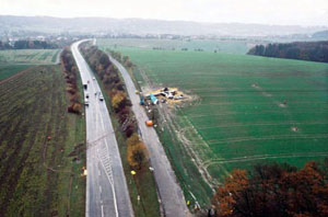
The aircraft touched down on a heading of approximately 295°, as indicated by the general direction of the debris. The first impact marks were found on the south edge of the road RN1. They represented the two main landing gears and the fuselage tail cone. Scraping marks on the road, notably from the left wing tip, showed that the aircraft slid across the road before hitting an embankment at the north side of the road RN1. The major part of the damage results from this impact during which the aircraft lost three blades from the right propeller and two from the left propeller as well as wheels from the left and right landing gear. Furthermore, the aft portion of the fuselage was disrupted at the trailing edge of the wings by this shock. After this bounce, the empennage and part of the right outboard wing broke away, the aft portion of the fuselage turned around to the right, and the aircraft came to rest 25 meters further away in a field.
An animation of the final minutes of the flight path is available below:
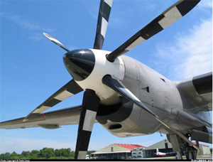
R352/6 propeller - Propeller shown in feathered position
Photo copyright M. Radzi Desa - used with permission
Propeller Control System
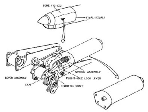
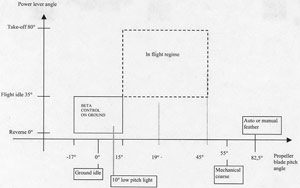
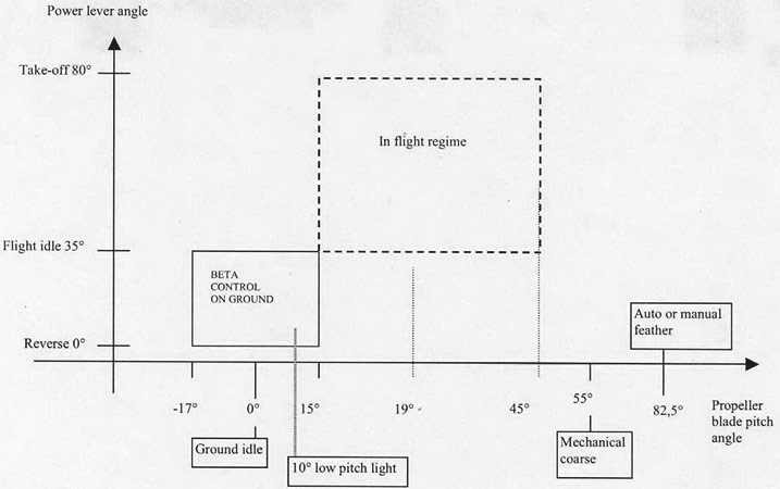
The PW 125B engines each drive a variable-pitch, constant-speed, six-bladed propeller. A propeller speed tachometer is located on the center main instrument panel. There are two control modes for the propeller:
- Above flight idle, constant speed control is regulated automatically in flight.
- On the ground, below flight idle and in the beta mode (reverse pitch) range, propeller pitch is directly controlled by the power lever position.
The actual blade angle at which the propeller produces zero thrust (torque) depends on the rotational speed of the propeller and the airplane forward speed. At a blade angle of approximately 26°, the propulsive force (thrust vector) acting on the airplane tends towards zero, and begins reversing direction if propeller pitch is further reduced.
In flight, power lever positions below flight idle are prevented by two means:

View Larger
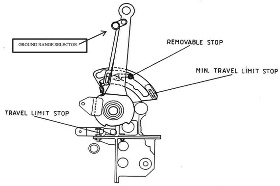
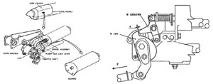
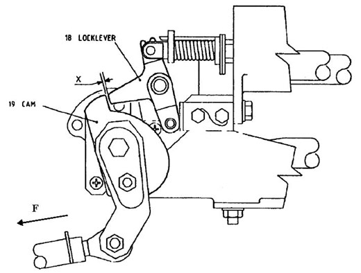
- A mechanical primary stop (ground range selector) on the power levers. This primary stop requires a positive, distinct and separate pilot action.
- An electrical secondary stop (flight idle stop solenoid) on each engine.
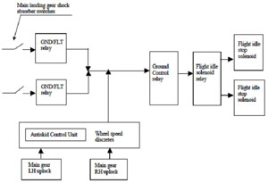
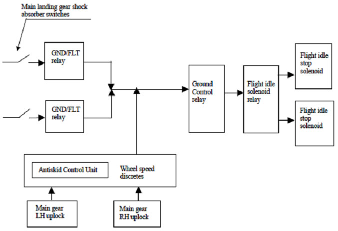
To select the beta mode (reverse pitch) after landing, with the power levers in the flight idle position, the pilot lifts the ground idle selectors and moves the power levers aft. The primary mechanical stop on the power levers is supplemented by a flight idle stop fixed to each engine and activated by solenoids. Once the solenoids are energized, the flight idle stops are moved, and power levers may be moved aft, into the range for reverse thrust. Power to the solenoids is supplied when:
- One of the sensors mounted on the shock absorbers of the left and right main landing gear detects a compression of the shock absorber during landing, or;
- The two wheel speed sensors, each one mounted in the wheel axle on one main landing gear, detect a wheel speed in excess of 17 knots.
(One per Engine - General, and Close-up Views)
View Larger: Image 1, Image 2
Above flight idle, the Propeller Electronic Control (PEC) unit controls propeller speed by varying the blade angle. Speed is controlled to 100% during take-off, maximum continuous, and go-around power settings. Propeller speed is controlled to 85% during climb and cruise. Propeller synchronizing is totally automatic.
Propeller pitch angle varies in flight from + 15° to approximately + 45°. Propeller pitch is controlled by balancing oil pressure against the coarse "seeking force" that results from the counterweights, which are attached to the roots of the blades. A high-pressure pump, driven by the propeller gear box and supplied with engine oil, provides the required oil pressure. In the event of an oil pressure loss, the counterweights will move the blades to an angle of + 55°, thus preventing propeller overspeed and minimizing the drag created by the windmilling propeller. The dedicated drive of the high-pressure pump assures control as long as the propeller is windmilling. In case of an in-flight engine failure, the propeller control mechanism initially tries to maintain a constant speed of the propeller in relation to the airspeed until it is feathered, either automatically or manually.
View Larger
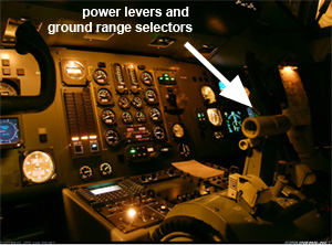
power levers and ground range selectors
Below flight idle, the power lever controls propeller pitch directly from a blade angle of approximately +15° to -17° (full reverse). In the beta mode, the commands of the propeller electronic controls are inhibited. Propeller blade angles are then solely controlled by the movement of the power levers (power lever angle). A blue low pitch light, located on the central instrument panel, comes on when the blade angle drops below 10°. During the investigation it was found that, while in flight with the power levers in flight idle, it is possible to lift the ground range selectors (primary lock) and move the power levers a small distance further aft until blocked by the secondary lock. This requires a deliberate action by the pilot, and is prohibited by the flight manual.
View Larger
In flight a propeller overspeed governor is activated when propeller speed reaches 104%. The gearbox-driven governor reduces the oil flow to the pitch changing mechanism. If there is no propeller speed reduction, the propeller speed reaches 108% and the overspeed governor intervenes directly in reducing fuel flow. On the ground, with the propeller in reverse pitch, overspeed protection is accomplished at 108% by reducing the fuel flow.
The propeller can be feathered either automatically or manually. The propeller is feathered manually when the fuel lever is set to SHUT or START. The feathering pump is activated when:
propeller in reverse pitch
- The autofeathering system is activated when the aircraft is on the ground or in flight, or;
- When the fuel lever is set to SHUT or START when the aircraft is in the air. The feathering pump brings the blade pitch angle to a position of 82° in order to minimize aerodynamic drag (feathered propeller).
A brief and very basic tutorial on relevant propeller control concepts and terms is available at the following link: Propeller Tutorial
An animation of the operation of the propeller in this accident is available at the following link below:
Electromagnetic Interference (EMI)
Electromagnetic interference is the disruption of operation of an electronic device when it is in the vicinity of an electromagnetic field (EM field) in the radio frequency (RF) spectrum. EMI can affect an electrical circuit due to either electromagnetic conduction or electromagnetic radiation emitted from an external source. The disturbance may interrupt, obstruct, or otherwise degrade or limit the effective performance of the circuit. The source may be any object, artificial or natural, that carries rapidly changing electrical currents, such as an electrical circuit, the sun, or the Northern Lights. EMI can occur unintentionally as a result of spurious emissions. It frequently affects the reception of AM radio in urban areas, and can also affect cell phones, FM radio, and television reception.
Radiated EMI may be broadly categorized into two types; narrowband and broadband.
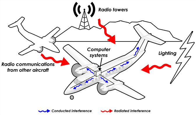
Narrowband interference usually arises from intentional transmissions such as radio and TV stations, pager transmitters, cell phones, etc. Broadband interference usually comes from incidental radio frequency emitters, such as electric power transmission lines, electric motors, thermostats, etc. Anywhere electrical power is being turned off and on rapidly is a potential source. Moderate- or high-powered wireless transmitters can produce EM fields strong enough to upset the operation of electronic equipment in close proximity. Cordless telephones, home entertainment systems, computers, and certain medical devices can fail to work properly in the presence of strong EM fields.
Conducted Electromagnetic Interference is caused by the physical contact of the conductors, as opposed to radiated EMI, which is caused by induction (without physical contact of the conductors). Electromagnetic disturbances in the EM field of a conductor will no longer be confined to the surface of the conductor and will radiate away from it. This persists in all conductors and mutual inductance between two radiated electromagnetic fields will result in EMI.
Existing Propeller Control System Anomaly
An EMI problem with the secondary flight idle stop on the F27 Mk 050 was identified as early as 1988. As the antiskid units powered up in response to landing gear extension, it was learned that if both units powered up within 20 milliseconds of each other, EMI resulting from this power up sequence could cause the ground control relay to activate, in turn causing the secondary lock to briefly release. In this situation, the secondary lock would be released for approximately 16 seconds. This could therefore result in a hazardous situation if the primary stops were intentionally released, and the power levers were held against the secondary stop with some force. This action was strictly prohibited by flight manual procedure, as follows:
Photo copyright Sven De Bevere - used with permission
"Do not attempt to select Ground Idle in flight. In case of failure of the flight idle stop, this would lead to loss of control from which recovery may not be possible."
When the service bulletin detailing modifications to correct inadvertent EMI-induced secondary stop activation was first introduced in 1992, it was not mandated. In 1993 Fokker received an incident report of power lever selection below flight idle during approach. Also, several airlines reported that ground range selector levers (primary stops) had been operated occasionally during flight, primarily in turbulence. In 1994 Fokker informed operators about the possibility of EMI-induced in-flight release of the beta lockouts, and recommended incorporation of the modification when an antiskid unit was removed or repaired for another reason. Following the accident, the modification was mandated by the European authority.
The Luxembourg Investigation Commission issued 15 findings. The key findings were:
- RVR was below approved company minima during the initial and the intermediate approach.
- During the approach, the crew deviated from the operator's SOP's.
- The captain resumed the final approach after having announced a go-around, without copilot's reaction.
- In order to achieve this goal, the crew performed several non-standard actions, amongst which the positioning of the power levers below flight idle. The AFM contained a limitation that prohibits the selection of ground idle in flight.
- The selection of the landing gear down triggered the deactivation of the second safety device (solenoid secondary stops), which was a possible malfunction identified by the manufacturer.
- The aircraft's drag increased significantly, and the aircraft's speed dropped as the rate of descent increased.
- Both engines were shut down by cutting the fuel flow.
The complete text of the findings is available at the following link: Findings
The Luxembourg Investigation Commission issued two reports. The original report was issued in December 2003 and is available at the following links: one for the report, and another for the associated appendices.
In July 2009 the commission issued a revised report. The complete text of that report is available here: Revised Report
The Luxembourg Investigation Commission issued several sets of recommendations relative to this accident, included in the original and revised accident reports. The principle recommendations in the original accident report were aimed at immediately mitigating (via crew awareness) and ultimately eliminating (via mandatory modification) the known EMI problem with the secondary flight idle stop. The complete text of these recommendations is available at the following link: Principle Recommendations
Additional recommendations in the original accident report were aimed at addressing both technical and organizational shortcomings deemed to contribute to the accident. The complete text is available at the following link: Additional Recommendations
A supplemental recommendation within the revised accident report was aimed at taking full advantage of radar surveillance through the implementation of formal procedures. The complete text of these recommendations is available at the following link: Supplemental Recommendation
- 14 CFR 25.1155 which reads:
"Each control for reverse thrust and for propeller pitch settings below the flight regime must have means to prevent its inadvertent operation. The means must have a positive lock or stop at the flight idle position and must require a separate and distinct operation by the crew to displace the control from the flight regime (forward thrust regime for turbojet powered airplanes)."
This is the same rule applied by the Joint Airworthiness Authority of Europe (JAA) (i.e., JAR25.1155 at Change 9) to certificate the Fokker F27 Mk 050. This rule is only intended to inhibit the inadvertent and not the intentional selection of beta. The primary mechanical flight idle stop on the Fokker F27 Mk 050 was found to meet this requirement. Due to industry-wide reports of pilots selecting reverse pitch in flight on a wide variety of turbo-propeller airplanes Fokker added the automatic flight idle stop to prevent intentional selection of beta in flight.
- The JAA JAR25.1155 at Change 16 (May 2003) which was adopted by EASA as the current CS25.1155 which reads:
"Each control for selecting propeller pitch settings below the flight regime (reverse thrust for turbo-jet powered aeroplanes) must have the following:
(a) A positive lock or stop which requires a separate and distinct operation by the flight crew to displace the control from the flight regime (forward thrust regime for turbo-jet powered aeroplanes), and it must only be possible to make this separate and distinct operation once the control has reached the flight idle position.
(b) A means to prevent both inadvertent and intentional selection or activation of propeller pitch settings below the flight regime (reverse thrust for turbo-jet powered aeroplanes) when out of the approved in-flight operating envelope for that function, and override of that means is prohibited.
(c) A reliability, such that the loss of the means required by sub-paragraph (b) above is remote.
(d) A caution provided to the flight crew when the means required by sub-paragraph (b) above is lost."
(e) A caution provided to the flight crew when a cockpit control is displaced from the flight regime (forward thrust regime for turbo-jet powered aeroplanes) into a position to select propeller pitch settings below the flight regime (reverse thrust for turbo-jet powered aeroplanes) outside the approved in-flight operating envelope. This caution need not be provided if the means required by sub-paragraph (b) is a mechanical baulk that prevents movement of the control.
This rule was the result of a joint industry and authority Aviation Rulemaking Advisory Committee (ARAC) recommendation to the FAA and JAA in response to a tasking by the FAA. This rule added a provision to the intent of the original rule to prevent both the inadvertent and intentional selection of beta outside the approved in-flight operating envelope for that function. This rule was deemed necessary by all parties to ARAC because flight crews had continued to intentionally select beta in flight despite procedures, training, and placards explicitly warning against and prohibiting such an action. This rule contains provisions for systems means to protect against flight crew selection of beta in flight as well as provisions to discourage the flight crews from relying upon those system protections, thus minimizing the critical exposure to any unanticipated system reliability problems which might develop (e.g., the Fokker F27 Anti-Skid System EMI problem).
- 14 CFR 35.21 which reads:
"Variable and reversible pitch propellers.
(a) No single failure or malfunction in the propeller system will result in unintended travel of the propeller blades to a position below the in-flight low-pitch position. The extent of any intended travel below the in-flight low-pitch position must be documented by the applicant in the appropriate manuals. Failure of structural elements need not be considered if the occurrence of such a failure is shown to be extremely remote under Sec. 35.15.
(b) For propellers incorporating a method to select blade pitch below the in-flight low pitch position, provisions must be made to sense and indicate to the flight crew that the propeller blades are below that position by an amount defined in the installation manual.
The method for sensing and indicating the propeller blade pitch position must be such that its failure does not affect the control of the propeller."
In this class of turbo-propeller airplane, propeller blade pitch has a significant effect on the aerodynamic performance of the airplane. Large disc areas extending in front of large areas of the wing could alter the lift characteristics of the wing, and at times, provide a performance advantage relative to descent rates and low-speed airplane handling characteristics. Also, over the time period of the late 1970s and early 1980s, a variety of new, large transport turbo-propeller designs became operational. Different from their earlier, smaller predecessor designs, these larger airplanes, employing higher horsepower engines and large-chord propeller blades, were more sensitive to the effects of propeller blade pitch. Where many earlier designs allowed (or at least, didn't explicitly prohibit) use of reverse pitch in flight, these new designs did not, and they were much less tolerant of the effects of in-flight reverse.
Over time, some flight crews of various models of turbo-propeller airplanes had learned that use of propeller pitch could be employed to a performance advantage in enhancing descent and field length performance. Use of in-flight reverse pitch, though generally prohibited operationally, had become somewhat widespread, and for the most part was successful in achieving the performance objectives of the flight crews. As this practice became more widespread, a number of accidents and incidents led to more operational emphasis on prohibiting the practice, and some design safeguards had been incorporated on various airplane models to physically prevent the use of in-flight reverse pitch. This did not lead to a complete cessation of the practice, however, and a small percentage of flight crews continued to employ whatever means was available to achieve low blade pitch (not always reverse) in order to maximize airplane performance.
- An unreliable secondary power lever stop that was susceptible to a specific failure mode (EMI) that resulted in it becoming ineffective in preventing the inadvertent (or deliberate) selection of in-flight reverse pitch
- Flight crews would follow limitations and procedures that prohibited the selection of reverse propeller pitch in flight.
- In the event of intentional override of the primary stop in flight, the secondary stop would prevent the inadvertent selection of reverse pitch while in flight.
Relevant Service Experience Prior to the Luxair Accident
There had been at least 11 fatal accidents dating as far back as 1951 related to propeller low pitch or reverse pitch settings in flight. One of these accidents involved a Fokker F27 Mk 200, which was type certificated 24 years before the Mk 050. There was also substantial in-service experience, as early as 1988, which identified EMI effects on the Fokker F27 Mk 050 antiskid system and the removal of the secondary pitch stops during landing gear extension. A Fokker service bulletin to correct this anomaly was issued in 1992.
With the exception of the Airworthiness Directives issued following this accident, there were no other regulatory or policy changes as a result of this accident. All the regulatory and policy changes required to prevent such accidents in the future had already been identified prior to the accident.
- Airworthiness Directive LUX-2002-001 was published on November 29, 2002, incorporating the provisions of:
- Fokker service bulletin Fo50-32-4-revision 1 from ABSC and
- Service bulletin N° F50-32-035 from Fokker Services B.V.,
- Airworthiness Directive LUX-2003-001 was published on May 12, 2003, incorporating the provisions of:
- Service bulletin N° Fo50-6004125-32-01 from ABSC and
- Service bulletin N° F50-32-038 from Fokker Services B.V.,
- Airworthiness Directive BLA Nr 2003-091, issued by the Dutch authorities on May 31, 2003, requiring incorporation of Fokker service bulletin N° F50-32-038.
- EASA Airworthiness Directive 2009-0049 was issued on March 2, 2009, mandating service bulletin N° F50-76-017 from Fokker Services B.V. be incorporated by March 16, 2011. This SB requires modification of the secondary flight idle stop system as well as the introduction of the additional monitoring and crew alerting features required to bring the F50 design into compliance with the latest EASA CS25.1155.
Airplane Life Cycle:
- Design / Manufacturing
- Operational
- Maintenance / Repair / Alteration
Accident Threat Categories:
- Uncommanded Thrust Reversal
- Incorrect Piloting Technique
- Lack of System Isolation / Segregation
Groupings:
- Loss of Control
- Approach and Landing
- Automation
Accident Common Themes:
- Human Error
- Pre-existing Failures
Human Error
The flight crew of Flight 9642 expected weather delays once arriving at their destination airport and had discussed the possibility of a hold or diversion to an alternate airport. After having been directed by air traffic control to hold, they were then unexpectedly cleared for the approach, even though the weather was below the required minimums for landing. Having reached the missed approach point, the captain elected to perform a go-around. As he initiated the go-around, the control tower called the flight and informed them that the weather had just gone above minimums and cleared the flight to land. The captain interrupted the go-around, and reinitiated the approach, though he was above the glide slope. As he reinitiated the approach, he lifted the primary propeller pitch stops, and moved the power levers back against the secondary stops, contrary to flight manual procedures which prohibited this operation in flight. As the landing gear was extended, EMI induced from the powering up of the antiskid control box caused the removal of the secondary pitch stops, allowing the power levers to inadvertently move into the reverse pitch range. As a result, airplane control was lost, and the crash occurred.
Pre-existing Failures
The accident airplane was equipped with an antiskid control box that was found to inadvertently emit EMI when going through its power up sequence. During the accident approach, when the landing gear was selected down (initiating the power up sequence on the antiskid box), EMI caused the removal of the secondary pitch stops, allowing the power levers, which were being held against the secondary stops, to move into the reverse pitch range. A loss of control, and the accident, resulted. The EMI-induced anomaly was known at the time, and Fokker had issued corrective service bulletins. The service bulletins had not yet been incorporated on the accident airplane, making it susceptible to the EMI-induced anomaly.
February 10, 2004, Fokker F27 Mk 050, operated by Kish Air
While on approach to Sharjah Airport in the United Arab Emirates, the airplane crashed approximately two- and one-half miles short of the runway. The investigation determined that the power levers had been in the reverse pitch range and were being held against the secondary pitch stops. At landing gear extension, the secondary stops had been removed due to the known EMI anomaly, resulting in the propellers moving fully into the reverse pitch range. The circumstances of this accident were almost identical to the Luxair accident. Although airworthiness directives had been issued by the Luxembourg authorities in 2002, and corrective service bulletins had been issued earlier, modifications had not been incorporated into this airplane. Kish Accident Report
May 26, 1991, Boeing 767-300ER, operated by Lauda Air
While climbing out after takeoff from Bangkok, Thailand, the left engine thrust reverser inadvertently deployed in flight. A loss of control ensued, and the airplane crashed. It was determined that failures of the thrust reverser control system led to a powered deployment event during climbout, and resulted in aerodynamic flow disruption over the left wing, leading to an uncontrollable lift asymmetry.
See accident module
There have been numerous other accidents since the 1950s, related to in-flight reversals on both turbo-propeller and turbo-jet powered airplanes.
Technical Related Lessons
In-flight propeller reversals on many types of turboprop-equipped airplanes induce an airplane response that can often have catastrophic consequences. For this class of airplane, safeguards should be sufficiently robust that an in-flight propeller reversal will not be expected to occur in the life of the fleet. (Threat Category: Uncommanded Thrust Reversal)
- In this accident, the flight crew was able to defeat the primary propeller stops in flight, and achieve a slightly lower propeller blade angle that may have improved the descent rate capability. However, by holding the power levers against the secondary stops (the only device remaining to prevent an in-flight reversal), the propellers would go into reverse pitch if the secondary stops should be removed. The landing gear extension caused a simultaneous power-up sequence in both of the antiskid control sensors, resulting in an EMI-induced removal of the secondary stops. The pilot pressure against the secondary stops resulted in power lever motion into the reverse pitch range, and an inflight reversal on both propellers. Forward motion of the power levers allowed one propeller to be moved out of reverse pitch, but the other did not recover. Shutting down both engines did not alleviate the problem, and airplane control was lost, resulting in the crash.
Strict adherence to approved flight manual limitations is imperative in order to maintain safety margins inherent in the airplane design. (Threat Category: Incorrect Piloting Technique)
- The design of the propeller reversing system on the accident airplane included two power lever stops. One required a manual movement of an interlock on the power levers. The second on each engine, was activated by airplane sensors when certain conditions (airplane on ground or wheel speed activation) were satisfied. Airplane flight manual procedures prohibited the activation of the primary (manual) interlock when in flight. In this accident in-flight activation of the primary interlock left the system dependent on the proper functioning of the secondary system, and susceptible to a failure of the secondary system. In manually overriding the primary system in flight, the captain defeated a key safety feature of the airplane, and unknowingly left the airplane susceptible to the EMI-induced failure of the secondary system.
Common Theme Related Lessons
For airplane safety systems that rely on multiple layers of redundancy to prevent a catastrophic event, it is essential that the capability of each layer of protection be maintained throughout the life of the fleet. If one of the protection features is known to be compromised, or susceptible to failure, action should be required to restore the lost system capability. (Common Theme: Pre-existing Failures)
- In this accident, an EMI-induced failure allowed the secondary power lever stops to be briefly removed during a critical phase of flight. Further, though there was a procedure prohibiting its in-flight use, the flight crew could, and occasionally did, override the primary power lever stops. In doing so, the airplane was left reliant on the proper functioning of the secondary system, which was susceptible to EMI. If the primary stops were overridden, and the secondary stops were inadvertently removed, as was the case in the accident, the entire protection system was compromised and an accident possible. The nature of the EMI-induced failure was known in 1988, and a service bulletin to correct the problem was issued, but not required to be incorporated fleetwide. Following the accident, actions were taken to ensure the incorporation of the modifications fleetwide.