
British Aircraft Corporation BAC 1-11
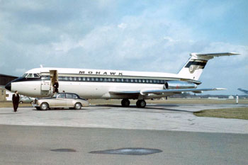
Mohawk Airlines, Inc. Flight 40, N1116J
Blossburg, Pennsylvania
June 23, 1967
On June 23, 1967, Mohawk Airlines Flight 40, a British Aircraft Corporation BAC 1-11, crashed approximately one mile east of the town of Blossburg, Pennsylvania. The aircraft was destroyed by impact and fire. All 30 passengers and four crewmembers on board the aircraft were killed in the accident. Weather was not a factor. The National Transportation Safety Board (NTSB) determined that the probable cause of the accident was the loss of integrity of the empennage pitch control system due to a destructive in-flight fire. The fire originated in the auxiliary power unit (APU) air inlet plenum chamber and propagated into an adjacent hydraulics compensator bay, then up into the vertical fin where it destroyed the components of the airplane's pitch control system. The fire resulted from engine bleed air flowing back through the APU in a reverse direction due to a malfunctioning APU non-return valve and an open APU air delivery valve.
History of Flight
Mohawk Airlines Flight 40, a BAC 1-11, was a regularly scheduled passenger flight originating in Syracuse, New York and destined for Washington, D.C., with an enroute stop at Elmira, New York. The flight from Syracuse to Elmira was routine in all respects, and the aircraft arrived at the Chemung County Airport at Elmira at 2:07 p.m. Prior to takeoff from
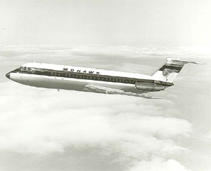
Photo copyright John Saunders, Airbus UK
- used with permission
Elmira, Flight 40 received an Instrument Flight Rules (IFR) clearance to Washington National Airport in accordance with the filed flight plan, with the exception that the flight was restricted in climb to maintain 6,000 feet, rather than the requested altitude of 16,000 feet.
Flight 40 departed Elmira on runway 24 at 2:39:40 p.m. Tower controllers, who observed the progress of the aircraft visually following its takeoff until it started a left turn toward the south, noticed nothing unusual with respect to the aircraft or its maneuvering. Following takeoff, Flight 40 was instructed by Elmira Tower to contact the New York Air Route Traffic Control Center. This contact was established at 2:42:28 whereupon the flight was cleared direct to Harrisburg. Flight 40 acknowledged this clearance and stated that they were climbing to 6,000 feet. This was the last communication from the aircraft.
At 2:47, the New York Center controller observed the radar target of Flight 40 appear to slow down for one sweep, then move laterally for one sweep, finally disappearing from the scope. Thereafter, the center controller vectored a small airplane over the area where Flight 40 had disappeared from the controller's screen. The pilot of this aircraft reported observing the burning wreckage of an airplane, which was later identified as Flight 40.
The aircraft crashed approximately one mile east of the town of Blossburg, Pennsylvania on a wooded hillside. Two witnesses, located on Highway 15 about two miles north of Blossburg, observed a large section of the upper tail assembly separate from the aircraft, after which some smaller pieces also came off the tail. The aircraft then nosed over and dove out of view. One of these witnesses also observed rust-colored fire and smoke emanate from the rear of the aircraft following the separation of the aforementioned sections of the tail.
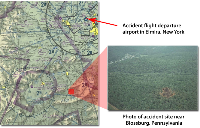
Photo copyright John Saunders, Airbus UK - used with permission
Investigation
The accident investigation focused on evidence of an in-flight fire originating in the auxiliary power unit (APU) airframe plenum chamber, and a damaged non-return valve that is designed to prevent engine bleed air in the aircraft air supply system from flowing in a reverse direction through the APU.
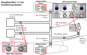
showing the main controls and valves
View Large
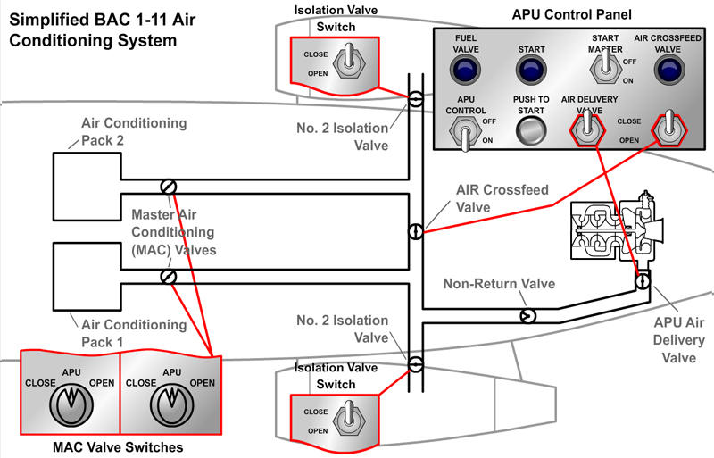
BAC 1-11 Air Conditioning System
The BAC 1-11 air supply system is arranged into two halves. Both are identical except for a ground starting connection in the number 2 (right) engine side, and an APU air supply connected to the number 1 (left) engine air main ducting. Air is supplied from each engine's high pressure compressor and controlled to a suitable temperature and pressure before passing to the air conditioning and hot-air ice protection systems. Engine air is ducted through two non-return valves, an isolation valve, a pressure-reducing valve, and a heat exchanger mounted in the engine stub fairing before entering the fuselage ducting. An air crossfeed valve connects the two halves so that supply air from one engine can crossfeed the other. The APU air supply can also be routed to the number 2 engine air conditioning system ducting through the crossfeed valve. The isolation valve isolates the engine from the rest of the aircraft air supply system. This allows operation of the air conditioning system from the other air supply sources without affecting the operation of the isolated engine.
The APU supplies air through an air delivery valve, at suitable pressure and temperature, to the aircraft main air supply ducting. The APU air output can be used for engine starting, air conditioning on the ground, and in flight up to 17,000 feet. The air delivery valve performs the same function as the engine isolation valve in that it isolates the APU from the rest of the aircraft air supply system. In addition to the pilot-operated air delivery valve, a non-return (check) valve is installed in the APU air supply ducting to prevent the higher pressure engine supply air from flowing into the APU in a reverse direction through an open-air delivery valve.
Two master flow control and shutoff valves, also called the Master Air Conditioning (MAC) valve, regulate air flowing into each of two air conditioning system refrigeration packs to a pressure of 50-55 pounds per square inch. Each MAC valve is controlled by a three-position switch, which is located in the flight deck overhead panel. The two MAC valve switches allow the pilot to select either engine bleed air (open position) or APU bleed air (APU position) as the air source for either or both air conditioning packs. These switches also have an off position, which isolates the system from all bleed air sources.
Auxiliary Power Unit Installation
Drawing by John Saunders, Airbus UK - used with permission
View Large
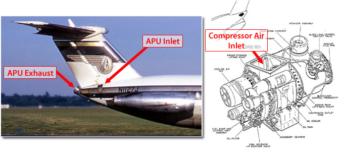
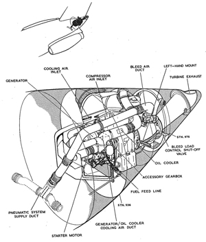
The BAC 1-11 APU is installed in the airplane's tail cone behind the engines and underneath the rudder and vertical stabilizer. The APU air inlet is located on the upper right-hand quadrant of the fuselage. It consists of a clamshell type door that opens upward into the airstream. The APU inlet directs air into a plenum chamber that is connected to the APU compressor air inlet.
Drawing provided by John Saunders, Airbus UK - used with permission
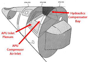
The plenum chamber was designed primarily to facilitate the smooth flow of outside air to the APU compressor inlet. Mounted on the inside of the inlet plenum chamber are acoustic liners, whose purpose is to reduce external noise levels during APU operation. Facing forward, the APU inlet plenum chamber is on the right-hand side of the fuselage, while a hydraulics bay is located on the left side. The hydraulics bay houses the hydraulic compensator units in the return lines from the airplane flight controls power control units.
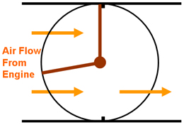
APU Non-Return Valve
The purpose of the APU non-return valve is to prevent higher pressure engine supply air from flowing into the APU in a reverse direction through an open-air delivery valve. The non-return valve consists of two flaps that are spring loaded to the closed position. Air flowing from the APU forces the flaps into an open position, allowing air to flow into the aircraft main air supply ducting. Valve seats prevent engine bleed air from flowing in the opposite direction.
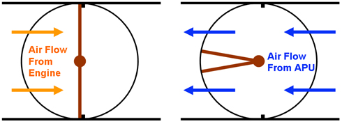
Non-Return Valve Accident Configuration
As found in the accident wreckage, one of the two valve flaps was forced down inside the intake ring while the other flap was partially open with some of the buckled ducting folded underneath it in a manner suggesting that the flap was partially open at impact. Investigators found deposits on the upstream or APU side of the valve flap, which was jammed shut and on the same side of the intake ring center web. These deposits were subsequently identified as nylon residue. Examination of the valve disclosed that both of the valve flaps were severely deformed, being cupped inward toward the intake ring so that the seat sides of the flaps were convex. The pattern of distortion was similar in both flaps, with the maximum bend being about 45 degrees. There was also some deformation of the seat areas on the flaps and on the intake ring. In addition, galling was present on the surfaces of the valve hinge ears of both flaps. The deformation allowed engine bleed air to flow past the non-return valve in a reverse direction toward the APU.
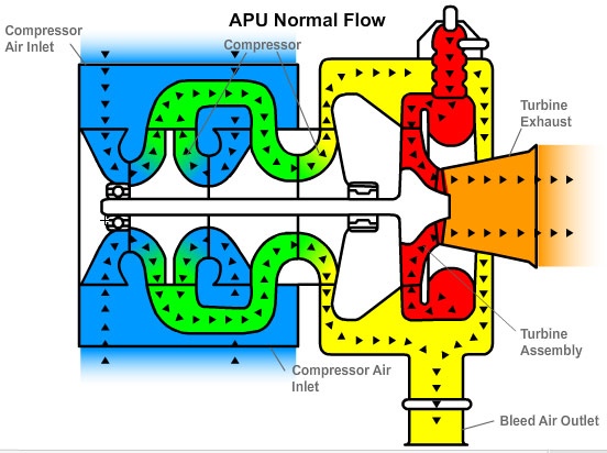
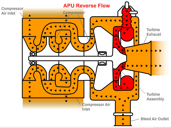
APU Reverse Flow
In normal operation, air flowing into the APU from the air inlet plenum is pressurized by a two-stage centrifugal compressor. The compressed air flows into the combustor where it is heated by burning fuel. This higher energy air drives a single stage turbine, which in turn drives the compressor. High pressure air for the aircraft air conditioning system is drawn through a bleed air outlet located between the compressor exit and the entrance to the combustor (APU turbine plenum).
During the course of the Mohawk Airlines Flight 40 accident investigation, the NTSB conducted a number of tests to determine the cause of the in-flight fire. An extensive series of tests were conducted on the APU to determine the effect of ingesting raw fuel, Skydrol hydraulic fluid, and acoustic linings (both dry and soaked with kerosene and Skydrol) into the compressor inlet of the APU during various induced surge and operating conditions of that unit. None of these tests produced ignition or flame propagation in the compressor inlet. However, during the course of these APU tests, the NTSB noted that it was possible to achieve a reverse airflow through the APU. They further observed that such reverse flow was accompanied by a temperature rise at the intake to the APU, or in what would be the airframe plenum chamber. On the basis of this information, the NTSB conducted an extension of these tests under still air conditions, utilizing a static mounted rear fuselage section of a BAC 1-11 in which an APU was installed. A hot air supply, simulating main engine bleed air was connected to the APU air supply ducting. The airframe plenum chamber in the fuselage was fitted with a full set of acoustic linings. Prior to each of the three tests that were conducted, these linings were injected with controlled amounts of aviation turbine fuel, Skydrol hydraulic fluid, and white spirit. In addition, a small quantity of Skydrol was applied to the walls and floor of the hydraulic compensator bay.
With the APU running in the no load condition and the air delivery valve selected closed, the pressure of the simulated engine bleed air in the delivery duct was raised to equal the pressure in the APU turbine plenum. The APU air delivery valve was then selected open and the simulated engine air pressure gradually increased until the APU compressor surged. The compressor surged at a turbine plenum static pressure of between 44 and 45 pounds per square inch gage (psig). At this pressure, the simulated main engine air flow into the APU turbine plenum increased rapidly from less than 1 pound per second to approximately 4 pounds per second due to a reduction in back pressure, and hot air was discharged into the airframe plenum chamber. When the surge point was reached, the APU appeared to flame out and drop to 95 percent speed, allowing automatic re-ignition to occur. The APU then recovered to a speed only slightly above normal, and continued to run with reverse flow conditions prevailing. Apparently, a portion of the simulated engine air was utilized to sustain combustion, while the remainder passed through the compressor section and into the airframe plenum chamber. View an animation of the BAC 1-11 APU reverse flow phenomenon below:
The NTSB testing established that simulated main engine bleed air, at temperatures as low as 160°C would exit at a temperature of 360°C into the airframe plenum chamber. The report states that the increase in air temperature probably resulted from the heat absorbed from the torus housing as the air passed through the APU turbine plenum chamber and from the work done on the air by the impeller blades as it passed in a reverse direction through the APU compressor.
Investigators determined that the elevated temperatures in the plenum chamber and hydraulic compensator bay created an environment in which the acoustic lining located on the wall separating these two compartments could be heated to the point of ignition. The investigators referred to this process as "self-heating." The elevated temperatures apparently produced a type of non-adiabatic process which provided not only a heat source, but also acted as an insulator on each side of the lining, thus causing it to gain more heat than it lost to its surroundings.
Tests indicated that the lining material ignited when the temperature on both sides of the blanket during reverse flow conditions was well below that which existed inside the lining material. Other tests indicated the lining material might heat to ignition if a one-inch thick slab was exposed on one side to 207°C, with the other side perfectly insulated, under still air conditions. The addition of contaminants, such as Skydrol and kerosene appeared to decrease the heating tendency of the linings. The measured self-ignition temperature in a hot air furnace of the acoustic lining assembly was 477°C. Combustion started in the center of the material and progressed outward.
Confirmation of this heating process was the fact that when the air temperature in the plenum chamber stabilized at 360°C, the temperature in the acoustic lining on the inboard wall continued to rise to 515°C. The NTSB also noted that several acoustic blankets removed from operational aircraft after the accident contained indications of heat damage, which they believed could have been caused by reverse airflow.
When the possibility of reverse air flow through the APU became apparent, a fleet inspection campaign was conducted to determine the condition of non-return valves on all BAC 1-11 aircraft in service throughout the world. The worldwide BAC 1-11 fleet at the time consisted of approximately 80 aircraft. Approximately 20 percent of the valves were serviceable and conformed to specifications. Sixty percent had deformed flaps, which would cause leakage, although not to an extent that would have rendered the valves unserviceable. The remaining 20 percent (approximately 16 valves) were deficient in a manner making them unserviceable.
Additional Tests and Research
The NTSB conducted flight tests to evaluate where leaking hydraulic fluid would go. One of these tests involved releasing dyed water in the area of the rudder power control units to simulate leaking hydraulic fluid. The bulk of the fluid drained into the hydraulic compensator bay where some of it was trapped in the inboard section of the bay due to an inadequate drainage system. The NTSB then checked all nine aircraft on the BAC 1-11 production line. They observed that the sealing between the hydraulic compensator bay and the airframe plenum chamber was imperfect, with the consequence that the trapped fluid, under ambient conditions, seeped into the APU airframe inlet plenum chamber. These flight tests were conducted with the plenum chamber acoustic lining installed, and some of the fluid became coated on, or was absorbed by, these acoustic linings.
The Skydrol brand hydraulic fluid, commonly used on transport aircraft and used on the BAC 1-11 airplane, is considered to be a fire-resistant hydraulic fluid in accordance with the standards set forth in Aeronautical Material Specifications (AMS) 3150c. These specifications prescribed that the autogenous ignition temperature of such a fluid must be higher than 750°F (399°C), determined in accordance with certain testing procedures. The manufacturer's tests of Skydrol indicated that the flash point of that fluid was 180°C, the fire point was 215°C, and the auto-ignition temperature was 496°C. However, Skydrol exposed to air at elevated temperatures will undergo thermal decomposition, and the flash, fire, and auto-ignition temperatures will decrease by as much as 9°C. Independent laboratory tests indicated that when Skydrol is heated, the flame retardants associated with that fluid are among the first of its basic components to vaporize.
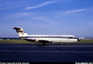
Photo copyright Bob Garrard - used with permission
Tests conducted during the investigation demonstrated that a jet spray of Skydrol flowing at a rate associated with a characteristic leak in a flexible hydraulic hose could be ignited by a propane flame, a high energy spark, or a hot wire source. Furthermore, when the ignition source was removed, the ignited Skydrol, with an air/fluid ratio of 300:1, would sustain a flame six to eight feet long.
The NTSB visually inspected approximately 34 sets of acoustic lining assemblies following their removal from operational aircraft. Approximately one-third of these sets contained areas of deterioration, some of which appeared to be caused by mechanical means, such as rubbing or sonic vibration, while other damaged areas appeared to have resulted from exposure to heat. Approximately one-third of the 34 sets also contained areas which were wetted or soaked with Skydrol. However, only three or four of the total number of sets exhibited both deterioration and Skydrol contamination.
The NTSB also conducted flight tests to determine airflow patterns within the airframe in order to determine the extent to which normal internal airflow contributed to the propagation of the in-flight fire. The flow patterns were deduced from static pressure measurements taken in the APU bay, the plenum chamber, the hydraulics bay, the rudder control unit bay, and the vertical fin. These tests verified the potential for a draft from the hydraulics bay up through the vertical fin. These tests also showed that the pressure in the hydraulics compensator bay was greater than the plenum chamber pressure, a differential which contributed to the seepage of leaked hydraulic fluid into the APU airframe inlet plenum.
Operational Factors
Before starting the engines in Elmira prior to the accident flight, the pilots noted an excessive reading on one of the main air duct pressure gauges. However, after trouble-shooting this problem, they reached the conclusion that it represented nothing more than a defective gauge. Such reasoning was logical and there is no reason to connect this occurrence with the subsequent fire. However, the captain's reference to a "hot start" that occurred "the last time" or presumably prior to the previous departure in Syracuse may be significant. Such a start usually results from an inadequate starter air supply, and thus may be symptomatic of a malfunctioning non-return valve. A non-return valve that fails to open fully would restrict the flow of air from the APU to the engine being started. If the engine was being started by air supplied from the other engine rather than air from the APU, the "hot start" may have resulted from some of the supply air leaking back through the non-return valve, which failed to close completely.
After starting the engines in Elmira, the pilots specifically referred to closing the isolation valves and, in accordance with standard procedures, these valves would have remained closed until after takeoff. Consequently, reverse air flow could not have occurred during this period. Moreover, there was no indication, either within or outside the aircraft, of a fire in the plenum chamber while the aircraft was on the ground.
The entire departure operation from Elmira, including ground procedures, takeoff, and initial climb, appeared to be routine. Assuming the crew operated the aircraft in accordance with standard procedures in effect at the time of the accident, they would have executed the after-takeoff checklist after raising the landing gear and reducing power to the climb setting, or about one minute after takeoff at an approximate altitude of 1,500 feet above the field. This checklist was not executed by the challenge and response method, but rather could be carried out by a single pilot with no oral reference being made to any of the checklist items. This accounts for the absence on the cockpit voice recording of any conversation concerning this checklist. In the process of completing the checklist, the pilots would have opened the isolation valves and switched the MAC valve switches from APU to open, thus allowing main engine bleed air to flow into the pneumatic system. The conclusion that the pilots took these actions is corroborated by the open position of the isolation valves and pressure reducing valves as found in the wreckage. It was at this point that reverse air flow would have begun with engine bleed air flowing back to the APU through the malfunctioning non-return valve and the open-air delivery valve.
The BAC Flight Manual and the Mohawk Airlines Operations Manual both provide that the APU air delivery valve should be closed when the pneumatic systems are switched from APU to engine bleed air after takeoff. However, these manuals also provided that the pneumatic systems may be left on APU air if the flight would remain below 10,000 feet, thus requiring that the air delivery valve also be left open. The NTSB report stated that the Mohawk pilots apparently construed these provisions, as reflected by their description of company policy, to allow the air delivery valve to remain open until a flight exceeded 10,000 feet, even on those flights on which it was intended to ultimately climb to an altitude above 10,000 feet. This could also be the case even if the pneumatic systems were switched to engine air shortly after takeoff. The NTSB believed that the pilots on the accident flight were utilizing such a procedure as evidenced by the fact that the air delivery valve was found in the wreckage to be in the open position.
The NTSB emphasized that initiation and continuance of reverse flow would not have been evident in the cockpit. The reverse flow tests demonstrated that the only indication of the commencement of this process, apart from the discharge of smoke, was a change in noise emission from the APU, which obviously could not be heard in the cockpit. There would also have been a slight drop in APU rpm prior to reignition, which likewise was not recorded in the cockpit.
Maintenance Records
The flight log sheets covering the several-month period prior to the accident contained a substantial number of discrepancies pertaining to the pneumatic system and APU of N1116J. It did not appear, however, that the number of write-ups on these components was disproportionate with other operational BAC 1-11 aircraft at the time. The NTSB report states that the frequency of these write-ups probably stemmed in large part from the fact that they involved a complex system that had been in operation only a short time.
The NTSB emphasized that the damage to the non-return valve on N1116J was not an isolated instance, but rather was representative of the condition of a substantial number of these valves when examined during the fleet inspection campaign conducted after the accident. The NTSB also noted that the non-return valve was considered an "on-condition" item, and thus was not subjected to periodic inspections.
Sequence of Events
The NTSB determined from its investigation that an in-flight fire originated in the APU airframe plenum chamber, burned through to the adjacent hydraulics compensator bay, and then migrated up into the vertical fin. The primary combustible fueling the fire was hydraulic fluid, which was fed under pressure when the flexible hoses in the hydraulics bay failed due to excessive heat. The mechanism that initiated this sequence of events was a malfunctioning APU non-return valve, which allowed engine bleed air to flow back through an open-air delivery valve, through the APU, and exit into the airframe plenum chamber at elevated temperatures. The temperatures introduced into the plenum chamber by the reverse air flow were sufficiently high to cause the acoustic blankets to ignite. As the fire spread upward along the inboard plenum chamber wall, heat would have become concentrated in the uppermost levels of the chamber until a hole was burned through the top fuselage skin, adjacent to a hydraulic hose exit hole. At about this same time, the vertical aluminum wall between the plenum chamber and the hydraulics bay would have melted due to the extreme heat. Once this wall was destroyed, flexible hydraulic lines within the hydraulics bay would have been exposed to the fire and would have also failed quickly due to the heat. Consequently, substantial amounts of Skydrol hydraulic fluid would have been fed under pressure to the fire. In addition, an updraft from the fire in the hydraulics bay would have created a "chimney effect" through the hydraulic hose exit hole in the top fuselage skin. This would have allowed the Skydrol-fed fire to burn intensely up into the vertical fin.
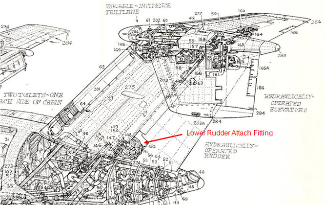
Drawing provided by Peter Clark, www.bac1-11jet.co.uk, from Mike Stanbrook
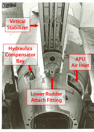
Photo copyright John Saunders, Airbus UK - used with permission
As the fire spread upwards through the vertical fin, the extremely high temperatures created by the fire would have destroyed the structural integrity of the lower rudder attach fitting and both vertical fin spars. The fire would have also destroyed the elevator control rods, the electric elevator trim lead, and both hydraulic systems, thus causing the pilots to lose all control of the pitch of the aircraft. The fire ultimately weakened the lower rudder attach fitting and the vertical fin spars to the point where those components failed under normal aerodynamic loading. The rudder, top two feet of the vertical fin, and the horizontal tail plane then separated in flight.
The NTSB made 12 findings from their investigation of this accident regarding the origin of a fire within the APU airframe plenum chamber and its propagation into the vertical fin, which resulted in loss of pitch control.
The NTSB determined that the probable cause of the accident was "the loss of integrity of the empennage pitch control systems due to a destructive in-flight fire which originated in the airframe plenum chamber and fueled by hydraulic fluid, progressed up into the vertical fin. The fire resulted from engine bleed air flowing back through a malfunctioning non-return valve and an open-air delivery valve, through the auxiliary power unit in a reverse direction, and exiting into the plenum chamber at temperatures sufficiently high to cause the acoustic linings to ignite."
The complete text of the Safety Board's findings may be read at the following link: Accident Findings
The complete NTSB accident report may be read at the following link: Accident Report
The NTSB issued three recommendations to isolate the vertical fin and hydraulic compensator bay from the APU airframe plenum chamber through the use of fireproof materials, and a restriction against the use of the APU in flight, until the recommended modifications could be made. The complete text of the NTSB recommendations, along with the FAA's written response to these recommendations in the accident report, may be read at the following link: Mohawk BAC 1-11 Accident Recommendations
The FAA certificated the Model BAC 1-11 in the United States under Civil Air Regulations (CAR) 4b, effective December 31, 1953, Amendments 4b-1 through 4b-11. The British Civil Aviation Authority (BCAA) originally type certificated this aircraft under its type certificate number BA3. The FAA validated this product under U.S. Type Certificate Number A5EU. The BCAA found compliance with the FAA type certification basis under the bi-lateral airworthiness agreement in effect at the time. The U.S. regulations contained the following provisions relevant to the NTSB findings on the Mohawk Flight 40 accident.
Section 4b.385 required design precautions to safeguard against the ignition of flammable fluids or vapors that might be liberated by leakage or failure in fluid systems. It also required design precautions to control any fire resulting from such ignition.
Section 4b.386 defined fire protection requirements for combustion heater installations. There were no specific regulations within CAR 4b applicable to auxiliary power unit installations, but the practice was to apply the basic powerplant installation requirements of subpart E of CAR 4b to an APU. However, it is interesting to note that paragraph 4b.386(c) required combustion air ducts to be of fireproof construction for a distance sufficient to prevent damage from backfiring or reverse flame propagation. As a result of this accident, this type of requirement was later applied to APU installations in § 25.1103(e) of part 25 in Amendment 25-46.
Section 4b.463 defined requirements for powerplant induction system ducts. This section contained two provisions that are relevant to the Mohawk Flight 40 accident. The first provision in § 4b.463(a) required drains in induction system ducts ahead of the first stage of a supercharger to prevent hazardous accumulations of fuel and moisture in the ground attitude. It is unclear as to whether or not this requirement for drainage of supercharger inlet ducts was applied to the BAC 1-11 APU inlet plenum. The Mohawk Flight 40 NTSB report states that it is probable that the acoustic linings on N1116J were contaminated with Skydrol hydraulic fluid, which had leaked into the plenum chamber due to inadequate drainage and imperfect sealing. The second provision in § 4b.463(d) required induction system ducts located within any fire zone, for which a fire-extinguishing system is required, to be fire resistant. The BAC 1-11 APU inlet plenum was located outside of the designated fire zone.
There were no specific requirements in CAR 4b to protect essential flight controls from the effects of fire.
The pilots of Mohawk Flight 40 did not adhere to the airplane flight manual instruction to close the APU air delivery valve after switching to engine bleed air after takeoff because of an apparent misinterpretation about the use of APU air supply in flight. From the number of APU non-return valves found in service with deformed flaps, the investigators concluded that flight crews may have been in the habit of operating the APU with the air delivery valve left open.
However, it was believed that damage to the non-return valve was caused primarily by repeated rapid closing and opening of the valve flaps caused by pressure fluctuations within the pneumatic system when the air source for the pneumatic system was switched between engine and APU, or when pressure from a given source varied rapidly.
- Operating procedures that did not clearly prohibit air conditioning system operation using engine bleed air with an open APU air delivery valve.
- Non-fireproof APU airframe inlet plenum, which allowed a fire to propagate outside the APU inlet plenum.
- Acoustic liners in the APU inlet plenum could absorb flammable fluids.
- Aircraft control system components not isolated by fireproof materials from areas subject to fire conditions.
- The APU non-return valve would prevent engine bleed air from reverse flowing into the APU.
- There would be no fires within the airframe plenum chamber.
- There were no common cause failure mechanisms that would result in the loss of pitch and yaw control.
There were numerous reports of discrepancies in the pneumatic system of N1116J, including the APU, prior to the accident. More specifically, during the period from April 1 to June 22, 1967, 55 of the 289 airplane logbook entries pertained to this system. Such write-ups included the following items:
- Low main duct air pressure when air was being supplied from the APU.
- APU would not hold both air conditioning packages.
- Excessive APU tailpipe gas temperature when both systems were on APU.
- APU generator disconnects with both MAC valves on APU.
- Excessive reading on main duct air pressure gauge (attributed to defective gauge).
- When MAC valve is switched from APU position to open position, or from closed to APU, there is a loud fluttering or chattering noise, and air pulsation is felt (this item appeared five times during the 10 days preceding the accident).
- Over-temperature on number 1 system but no system fails and shutdown.
- Repeated failure of number 1 system.
Several of these discrepancies could reasonably have been construed as evidence of a malfunctioning non-return valve. The loud fluttering or chattering noise in item 6, when the MAC valve selector was switched from APU to open or from closed to APU, may have been the erratic movement of an improperly operating non-return valve responding to pressure fluctuations. In addition, the repeated citations of the APU failing to supply adequate air pressure may have been caused by the failure of a sticking non-return valve to open fully, thus restricting the flow of air from the APU into the pneumatic system.
The FAA issued the following regulatory changes after the Mohawk Flight 40 BAC 1-11 accident:
§ 25.863 Flammable fluid fire protection. The FAA substantially rewrote section 25.863 in amendment 25-23, which became effective on May 8, 1970, to address flammable fluid leakage or vapors in areas of the airplane outside of designated fire zones. The basic rule requires means to minimize the probability of ignition of flammable fluids or vapors that might escape by leakage of a fluid system, and the resultant hazards if ignition does occur. In Amendment 25-46, effective December 1, 1978, the FAA added a new paragraph (d), which requires an applicant to identify and define each area where flammable fluids or vapors might escape by leakage of a fluid system.
§ 25.865 Fire protection of flight controls, engine mounts, and other flight structure. The FAA added this new section to part 25 in amendment 25-23 to require essential flight controls located in areas adjacent to designated fire zones that would be subjected to the effects of fire to be constructed of fireproof material or shielded so that they are capable of withstanding the effects of fire. This requirement was originally proposed before the Mohawk Flight 40 accident during an FAA-industry conference on April 25-29, 1966. However, the FAA issued the Notice of Proposed Rulemaking (NPRM) after the accident on August 22, 1968. In the NPRM, the FAA explained that the existing regulations did not require protection of engine mounts or control systems from the effects of fire. The need for this protection was highlighted when the flight crew of a jet transport airplane experienced control problems after aluminum aileron rods located outside of the fire zone became distorted due to heat from an engine fire.
§ 25.901(d) Installation. In Amendment 25-46, the FAA added a new paragraph (d) to section 25.901, which requires each APU installation to meet the applicable provisions of subpart E to part 25. The FAA's intent was to make it clear that subpart E of Part 25 contains provisions applicable to APU installations.
§ 25.1103 Induction system ducts and air duct systems. The FAA amended section 25.1103 in amendment 25-46, which became effective on December 1, 1978, to provide more comprehensive standards for APU induction system ducts. These standards were proposed during the airworthiness review program of 1975, and address several of the unsafe conditions that allowed fire to start within the APU plenum chamber and escape into adjacent areas. The rule addresses these unsafe conditions in two ways by:
(1) Preventing the presence of hazardous quantities of flammable fluids in APU induction system ducts, and
(2) Requiring APU induction system ducts to be fire proof for a sufficient distance upstream of the APU compartment to prevent hot gas reverse flow from burning through APU ducts and entering any other compartment of the airplane in which a hazard would be created by the entry of hot gases.
Specifically, with respect to preventing hazardous quantities of flammable fluids, the rule requires a drain upstream of the APU compressor to prevent the hazardous accumulation of fuel and moisture in the ground attitude and each induction system duct to be constructed of materials that will not trap or absorb hazardous quantities of flammable fluids.
AD 68-01-01, effective January 3, 1968, required a number of operational and design changes to prevent heat damage or possible fire in the airframe plenum chamber of the APU and migration of a fire into the vertical fin.
AD 68-01-01 R1, effective July 18, 1988, revised the original AD to include additional modifications to the APU installation and hydraulic compensator drain box and drain outlet.
The full text of AD 68-01-01 R1 may be read at the following link: AD 68-01-01 R1
Airplane Life Cycle:
- Design / Manufacturing
- Operational
Accident Threat Categories:
- Uncontrolled Fire / Smoke
Groupings:
- N/A
Accident Common Themes:
- Flawed Assumptions
- Pre-existing Failures
Flawed Assumptions
It appears from the NTSB accident report that the airplane manufacturer had assumed the airplane would be operated in such a manner that the APU would not be dependent on the continued functioning of the non-return valve to prevent reverse flow to the APU. While the non-return valve performed as designed, the manufacturer did not anticipate the amount of wear and damage that would occur from long-term exposure to repeated rapid closing and opening of the valve flaps, which resulted in repeated hammering of the flaps against the intake ring and repeated hammering together of the opening stops. Other flawed assumptions that can be inferred from the accident report are:
- Flight crews would close the APU air delivery valve after switching to engine bleed air in accordance with the operating manual, and not continue to operate the pneumatic system with all air source valves open.
- The APU would not reverse flow without resulting in an APU operating in an off-design condition and shutdown.
- There would be no fires within the airframe plenum chamber.
- There were no common cause failure mechanisms that would result in the loss of pitch and yaw control.
According to the NTSB report, the flight crew of the accident aircraft apparently interpreted the Mohawk Airlines operations manual, as reflected by their description of company policy, to allow the APU air delivery valve to remain open until a flight exceeded 10,000 feet. This interpretation also included those flights in which the crew intended to ultimately climb to an altitude above 10,000 feet, and on which the pneumatic systems were therefore switched to engine air shortly after takeoff. Manufacturers design the APU bleed air system for primarily ground use to allow operation of the air conditioning system at the gate while the main engines are not running. However, most APUs are also certificated for limited in-flight use. Such was the case with the BAC 1-11 APU, which may be operated in flight up to a maximum altitude of 10,000 feet. The altitude limit is based on the capability of the APU to supply the aircraft air conditioning system without exceeding its own operating limits. The fact that the airplane flight manual allowed use of the APU bleed air supply in flight did not negate the main instruction that the APU air delivery valve should be closed when the pneumatic systems are switched from APU to engine bleed air after takeoff. The flight crew incorrectly assumed that it was acceptable to operate the engine bleed with the APU air delivery valve left in the open position.
Preexisting Failures
The flight log sheets covering the several-month period prior to the accident indicate that the APU non-return valve on N1116J had been malfunctioning prior to the accident flight. A fleet inspection campaign after the accident found 20 percent of the non-return valves in service (approximately 16 valves) were deficient in a manner making them unserviceable.
On March 17, 1989, the flight crew of a Continental Airlines Boeing 737 safely returned to the departure airport after experiencing severe vibrations after takeoff. The flight crew was not aware that an APU fire had occurred at the gate prior to starting the main engines. About one-half of the underside of the elevator and trim tab were severely damaged. The tail cone was charred and blistered over a three foot by three foot area. The NTSB investigated this event as an accident and found that the APU combustor cap drain was clogged with several pieces of room temperature vulcanizing (RTV) material used as a potting compound in the APU buildup process. The NTSB determined that the probable cause of the accident was the ignition of puddled fuel from a blocked combustor drain line and a slow start during which fuel was misted and blown out of the APU tail pipe. An existing tailwind at the gate allowed the fuel to wet the tail surfaces and be ignited during APU start.
Technical Related Lessons
Auxiliary power unit induction system ducting must be fireproof for a sufficient distance upstream from the APU in order to protect against the effects of hot gas reverse flow. (Threat Category: Uncontrolled Fire)
- This accident represented a significant fire protection lesson associated with reverse flow of hot gases through an APU gas turbine. Prior to this accident, this failure mode was not anticipated by the regulations, or the design. The APU or cabin heater on piston-engine transport airplanes and early jet transports was commonly installed within the fuselage contour. Though protected in fireproof enclosures, these locations were not totally isolated from the aircraft cabin. Since the Mohawk Flight 40 BAC 1-11 accident, most manufacturers install the APU in the tail of the airplane aft of the pressurized cabin and behind the horizontal and vertical stabilizer control surfaces a sufficient distance to minimize damage in the event of an APU tailpipe fire or other APU failures. Some APU installations also include inlet temperature sensors that automatically shut down the APU when the temperature, or rate of temperature increase, exceeds a preset limit as the result of a reverse flow condition.
Common Theme Related Lessons
Repeated maintenance write-ups and corresponding maintenance actions that do not lead to resolution of the problem should trigger a more in-depth investigative process, leading to a positive resolution. (Common Theme: Pre-existing Failures)
- Prior the accident, there were 55 maintenance write-ups concerning anomalous behavior of the air conditioning system. Five times during the preceding ten flight days, a specific complaint regarding apparent valve chattering and intermittent airflow was written relative to engaging or disengaging APU airflow for air conditioning. The specific malfunction was determined by the investigation to have been a malfunctioning non-return valve which was chattering during changes in airflow. Maintenance performed following these maintenance write-ups was ineffective in discovering, and correcting, the actual cause of the malfunction.