
Boeing Model 737-3B7
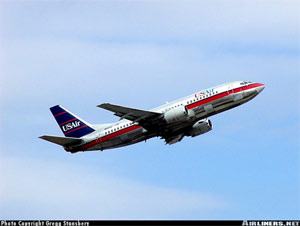
Photo copyright Gregg Stansbery - Used with permission
USAir Flight 427, N513AU
Aliquippa, Pennsylvania
September 8, 1994
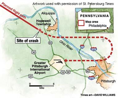
USAir Flight 427 crashed while on approach to Pittsburgh International Airport following a loss of control and airplane stall precipitated by an encounter with the wake of a preceding Boeing Model 727 airplane. The National Transportation Safety Board deemed that the loss of control was caused by a full rudder deflection in a direction opposite to that commanded by the flight crew (rudder reversal) in response to the wake encounter. During the upset, the elevator was commanded by the flight crew to its full-up position, resulting in an airplane stall, further compounding the loss of control. Control was never regained. The airplane crashed approximately six miles northwest of the airport, killing all 132 passengers and crewmembers. Subsequent to the accident, the Model 737 rudder system was redesigned to preclude an in-flight reversal. In addition, a training document, the Upset Recovery Training Aid, was produced by an industry team to aid in the development of training for recovery from in-flight upsets.
History of Flight 427
On September 8, 1994, USAir (now US Airways) Flight 427, a Boeing Model 737-3B7 airplane (Model 737-300 series airplane), N513AU, crashed while maneuvering to land at Pittsburgh International Airport in Pittsburgh, Pennsylvania. Flight 427 was operating under the provisions of part 121, "Operating Requirements: Domestic, Flag, and Supplemental Operations," Title 14 Code of the Federal Aviation Regulations (14 CFR 121), as a scheduled domestic passenger flight from Chicago O'Hare International Airport in Chicago, Illinois to Pittsburgh. The flight departed at approximately 1810 with two pilots, three flight attendants, and 127 passengers on board. While maneuvering during approach, the airplane entered an uncontrolled descent and impacted terrain near Aliquippa, Pennsylvania about six miles northwest of the destination airport. All 132 people on board were killed; the airplane was destroyed by impact forces and fire. Visual meteorological conditions prevailed for the flight, which operated on an instrument flight rules flight plan.
The National Transportation Safety Board (NTSB) concluded that the probable cause of the crash was a full rudder deflection in a direction opposite to that commanded by the flight crew (rudder reversal). This deflection resulted in a loss of airplane control.
Flight 427 was the third flight of the day for this airplane, having originated in Jacksonville, Florida as Flight 1181. Coincidently, this was the third day of a three-day sequence for the flight crew. Flight 1181 proceeded from Jacksonville to Charlotte, North Carolina, and then continued to Chicago. At O'Hare the flight number changed to Flight 427, and Pittsburgh was the final destination for the day. Flight 427 departed Chicago at approximately 1810 for a planned flight of 55 minutes. The flight proceeded uneventfully until final maneuvering for traffic separation and sequencing for landing in Pittsburgh.
Just prior to the loss of control, Flight 427 was maneuvering to land and was in a flight pattern four miles behind a Boeing Model 727. Flight 427 was flying at an indicated airspeed of 190 knots at "Flaps 1" (the one-degree position), which results in flap travel to a deflection of one degree and extension of leading-edge devices to the "sealed" (partially extended) position. Flight 427 had just been instructed to turn left to a heading of 100 degrees to follow a Delta Airlines Model 727. The heading change was intended to put Flight 427 on downwind for the active runway and in trail of the Delta flight for landing sequencing. The Delta flight had made the same maneuver, at approximately the same altitude, about 90 seconds prior to Flight 427 being instructed to turn to the same heading.
As Flight 427 was completing its turn, rolling through seven degrees of bank toward a wings-level attitude, the cockpit voice recorder (CVR transcript) recorded three "thumps" followed by exclamations from both pilots. (1) At the same time, the airplane experienced a three-knot fluctuation in airspeed that lasted about three seconds. The thumps and airspeed fluctuation were later determined to have been the result of Flight 427 passing through one of the vortex cores formed in the wake of the Delta Model 727. The airplane's left bank angle then increased from slightly less than eight degrees to slightly more than 20 degrees. (2)
Over the next eight seconds, the left bank decreased to approximately 15 degrees, and the heading rate increased to the left, passing through the assigned heading of 100 degrees. The airplane began to roll more rapidly to the left, and the heading (turn) rate increased to approximately five degrees per second as the heading passed left through 089 degrees. At the end of the eight-second period, the stick shaker (stall warning) activated, while the airplane continued to roll left with several fluctuations in the roll rate. The bank angle increased to over 40 degrees, and the airplane began to descend from its assigned altitude of 6,000 feet. The airspeed decreased to 186 knots, and the bank angle continued to increase. (3) The CVR recorded what appeared to be stall buffet increasing in amplitude and an autopilot-disconnect warning horn followed by an automatic traffic alert. The stall warning continued to the end of the recording. Twenty-eight seconds following the initial wake turbulence encounter, Flight 427 impacted hilly, wooded terrain approximately six miles northwest of the Pittsburgh airport at an altitude of 930 feet. (4) (5) An NTSB animation of the airplane flight path is available below. (CVR Sequence Photos).
Wake Turbulence
Early in the accident investigation it was surmised that Flight 427 had encountered the wake from the preceding Model 727. It was later determined, coincidental to wake vortex testing, that the "thumps" recorded on the CVR were the impacts of the concentrated, high-velocity airflow of the core of at least one of the wingtip vortices from the Model 727.
An airplane in flight, as a consequence of producing lift, displaces a volume of air equal to the weight of the airplane. A result of this displacement is a wake, similar in nature to the wake left behind a ship as it moves over water. The primary component of this wake is a pair of horizontal vortices that begin at the trailing edge of the wing near the wing tip. They can be described as "horizontal tornados," and they contain a great deal of energy-sufficient to affect the flight path of an airplane that flies through them. If the weight difference between two airplanes is substantial, a lighter airplane encountering the wake of a heavier airplane can be dramatically upset from its intended flight path.

View Larger
If the vortices were visible, viewed from behind an airplane, they would form near the wing tips and would appear to rotate in opposite directions-the vortex on the left wing rotating clockwise and the vortex on the right-wing rotating counter-clockwise. An airplane encountering a wake vortex in a longitudinal direction, that is, parallel to the direction of flight, would primarily experience a roll in the direction of rotation of the vortex encountered. If encountering a wake in a transverse direction (crossing the wake), the primary effect would be to experience a pitch up then a pitch down, based on the counter-rotating nature of the vortices. Encounters at oblique angles would result in combinations of these two effects. Once produced, the wake vortices can remain for several minutes, remaining longer in calm air than in air that is disturbed by winds or turbulence.
It is believed that Flight 427, in completing its turn to roughly the same heading as the earlier Model 727, encountered the wake vortices of the Model 727 and rolled to the left. This left roll was countered by the flight crew by applying right wheel and right rudder. In commanding right rudder, by pushing on the right rudder pedal, the NTSB believed that a failure in the rudder power control unit resulted in a rudder reversal. The reversal would have caused a full left rudder deflection when the pilot was commanding a full right rudder deflection. The reversal would have persisted for the entire time that the pilot continued to push on the right pedal, and would result in a left roll that, given the airspeed at the time, would not be easily controlled. As speed further deteriorated, control would become more difficult. It is also believed that the airplane was stalled in the first few seconds following the wake encounter, making recovery from the upset impossible until correcting the stall condition by reducing the angle of attack.
Hydraulic System and Rudder Control System
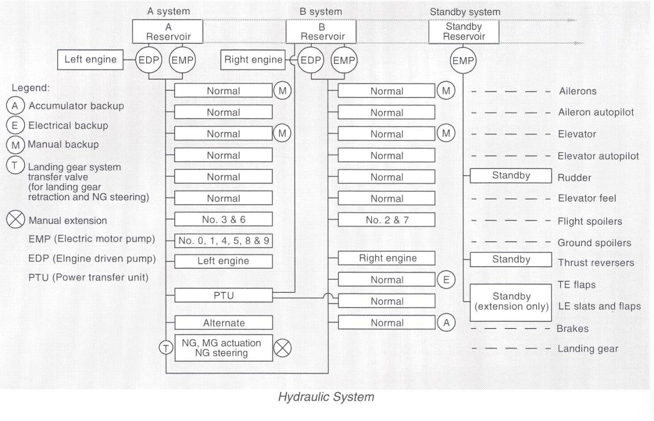
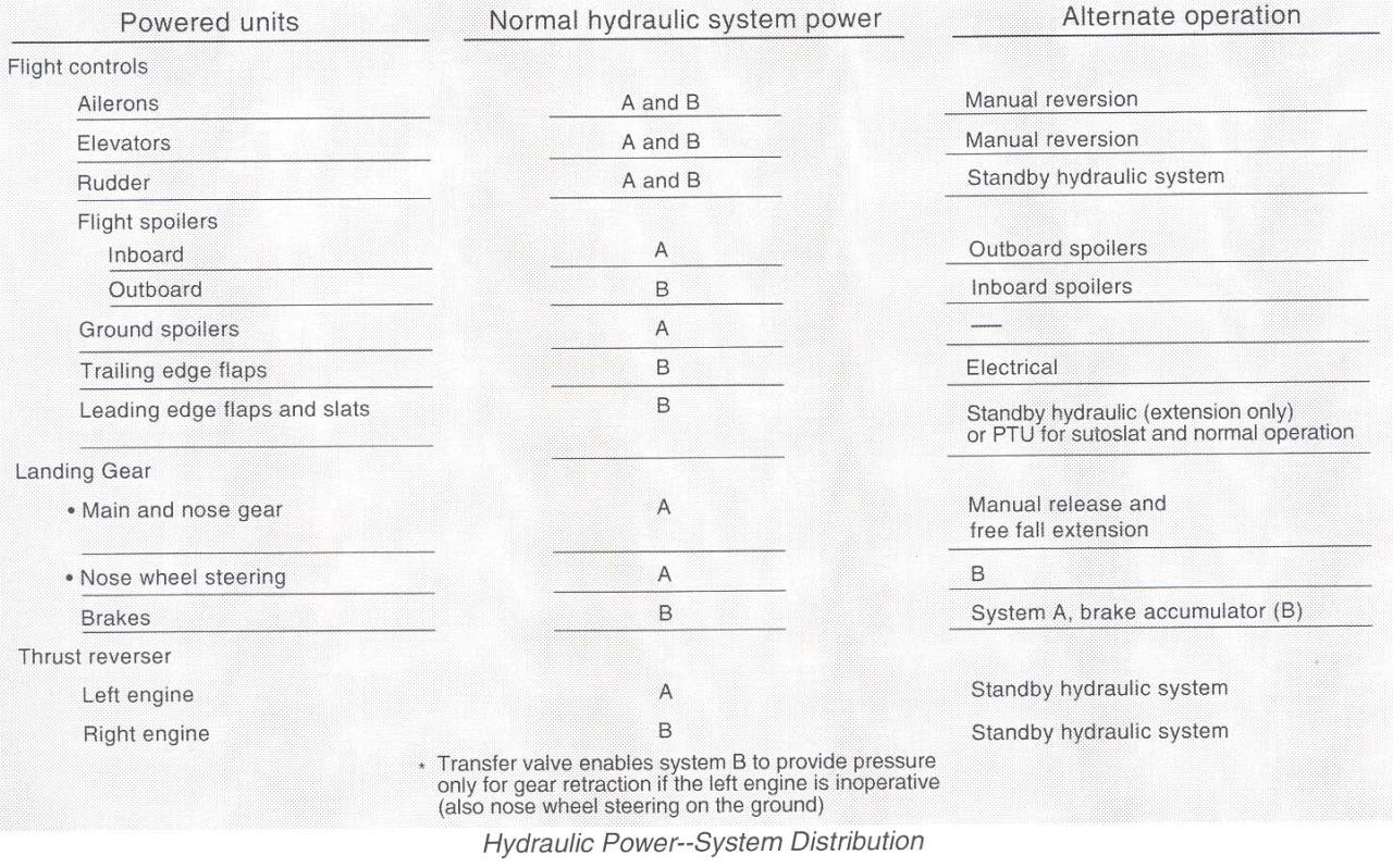
The hydraulic system on Boeing Model 737 airplanes is divided into three independent systems designated A, B, and Standby. Systems A and B each use one alternating current (AC) electric motor pump and one engine-driven pump to provide hydraulic power to their associated systems. The standby system uses a third AC electric motor pump, and, at the time of the accident, was activated by either the flight controls or alternate flap switches in the flight deck. Each system also contains a fluid reservoir. The reservoir for A and B systems is pressurized by regulated air from the environmental control system. The standby reservoir is pressurized by the fluid in the B system reservoir. Both systems A and B normally provide hydraulic power to the flight controls, however, either system alone is capable of powering the ailerons, elevator, or rudder. As an additional backup, the ailerons and elevator can be operated in a manual reversion (unpowered) mode and the rudder operated by the standby system. Schematics of the hydraulic system and distribution of the hydraulic supply from system A or B and the standby system can be found at the following links: (Model 737 Hydraulic System) (Model 737 Hydraulic Distribution).
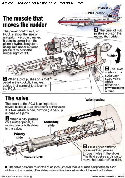
The rudder system operates via manual rudder pedal inputs through a hydraulically powered rudder. There are two sets of rudder pedals, one for each pilot. Either set of pedals provides inputs to the rudder power control unit (PCU) via cables routed through a control quadrant located in the back of the airplane, and then via an input control rod between the aft quadrant and the PCU itself. The rudder system is normally hydraulically powered by both the A and B hydraulic systems, or, following a hydraulic system failure, through the standby rudder system. The PCU operates through a dual-load path mechanical linkage operated by either the rudder pedals or the yaw damper. A yaw damper system operates through the B hydraulic system in the main PCU. The yaw damper is independent of the pedals and does not result in feedback at the pedals.
Rudder trim is controlled by an electromechanical actuator from the trim knob located in the flight deck. It repositions the feel and centering unit to a new neutral point, which in turn repositions the rudder. Rudder feel (rudder force) is provided by a mechanical feel and centering unit. A document providing a progressively detailed overview of the rudder system is provided at the following link: (Model 737 Rudder System Overview).
Rudder Power Control Unit
The rudder PCU is a moving, hydraulically controlled piston, with the actuator rod end attached to the rudder and the PCU body attached to airplane structure. The PCU provides the motive power to move the rudder surface when commanded by either the pilot (via the rudder pedals) or the yaw damper. A pilot input at the rudder pedals is transmitted through a cable run, which extends to the aft control quadrant connected to the aft torque tube to an external summing lever.
The "heart" of the PCU is the main control valve, consisting of two concentric valves, one inside the other, and both inside a case. The valve allows metered hydraulic fluid flow and supplies pressure to move the rudder in the commanded direction. The main control valve is divided such that each hydraulic system provides pressure to half of the concentric pair. The inner valve is called the primary slide, and the outer is called the secondary slide. Inputs to the main control valve are through a dual input linkage, the primary summing lever providing input to the primary slide and a secondary summing lever providing input to the secondary slide. In a case where the rudder is not required to move at a high rate, only the primary slide moves. With a high-rate demand, the primary slide moves to its travel limit, and then the secondary slide moves, allowing a higher hydraulic pressure and more rapid rudder movement. Position feedback is provided by a mechanical summing linkage attached to the main rudder actuator piston rod. A graphical depiction of the internal mechanism of the PCU and an animation of the entire PCU during normal function are available below: (Boeing PCU Animation) (PCU Internal Mechanism Animation) (PCU Internal Mechanism Diagram). The animation is approximately six minutes long. It displays the various operational input modes to the PCU and how rudder commands are created through the PCU.
The entire rudder system is designed such that total rudder travel is limited as a balance between airspeed (dynamic pressure against the rudder surface) and system hydraulic pressure (3,000 psi). At lower airspeeds the rudder system has sufficient hydraulic pressure to attain the physical rudder travel limit of 28 degrees. At higher airspeeds system hydraulic pressure is insufficient to move the rudder to its physical limit, and travel is limited by air loads. This phenomenon is known as rudder blowdown. At the flight conditions of Flight 427, the maximum available rudder deflection, due to blowdown, was approximately 15 degrees.
The concentric servo valves inside the rudder PCU operate in tandem to allow hydraulic flow and deflection of the rudder. If either valve fails to function properly, it can result in an improper rudder deflection, or apparent jam. In the case of Flight 427, the NTSB concluded that the secondary slide jammed against the valve case, while the primary slide moved in its normal direction. The jam of the secondary slide allowed the primary slide to "overtravel," that is, moving to a position that prevented proper alignment of the fluid ports on each valve. This caused a flow of hydraulic fluid in a direction that was not intended and resulted in a rudder deflection to the rudder blowdown limits that was opposite to what the flight crew commanded - a rudder reversal. The mechanics of a rudder reversal are provided in the diagram to the right. Once deflected, as long as the pressure was maintained on the rudder pedals, the rudder deflection would be maintained, and, to the flight crew, the rudder would appear to be jammed. In the Flight 427 situation, it was postulated that the flight crew commanded a right rudder deflection to correct the left roll. But, due to the reversal phenomenon, the rudder went to its fully deflected position (the blowdown limit) to the left. As the airplane response was now to the left, rather than the right as desired by the flight crew, the pilot would have maintained the pressure on the right pedal, thereby maintaining the "jam." Furthermore, it was learned during laboratory tests duplicating the reversal phenomenon that rudder deflection was fed back through the pedals, so that while the pilot was pushing on the right pedal, the system, including the pedals, was moving as if he were pushing on the left pedal. The following NTSB animation depicts this phenomenon, showing both normal rudder usage and required pilot effort, contrasted with a rudder reversal scenario and the forces exerted by the rudder system in resistance to pilot effort.
Crossover Speed
To further complicate the issue, the configuration and flight speed (flaps 1 and 190 knots) put the airplane in a flight regime where a fully deflected rudder would overpower the lateral control system. This phenomenon came to be identified as the "crossover speed," or the speed at which the lateral control system (ailerons and roll spoilers) could exactly balance the available full rudder deflection. Flight 427 was almost exactly at this crossover speed when the wake encounter and the subsequent full rudder deflection occurred. A small speed loss allowed the rudder to overpower the opposing roll control inputs, and the roll to the left became uncontrollable. If the airplane had been accelerated just a few knots, the roll control authority would have increased sufficiently for the rudder-induced roll to have been countered. However, being in the critical speed area at or near the crossover speed made any speed variation critical and airplane control difficult.
The NTSB ultimately determined that the combination of full rudder deflection, the confusion associated with an unknown flight control anomaly (rudder reversal), and a subsequent stall resulted in a loss of control and the crash.
The NTSB concluded that the probable cause of the Flight 427 accident was a loss of control of the airplane resulting from the movement of the rudder surface to its blowdown limit. The rudder surface most likely deflected in a direction opposite to that commanded by the pilots due to a jam of the main rudder PCU servo valve secondary slide to the servo valve housing offset from its neutral position and overtravel of the primary slide.
The complete NTSB report on this accident is provided at the following link: (usair427_ntsb_report.pdf).
The NTSB issued 34 findings relative to this accident. Of these findings, some were also issued relative to two other accidents/incidents: United Airlines Flight 585 (accident), which occurred near Colorado Springs, Colorado on March 3, 1991, and Eastwind Airlines Flight 517 (incident), which occurred near Richmond, Virginia on June 9, 1996. Due to similarity between these events and Flight 427, they were included in the accident investigation, and conclusions reached relative to Flight 427 were also considered applicable to the other two events. The 34 findings dealt primarily with perceived rudder system design deficiencies, rudder system jams, flight crew training relative to flight control jams, and deficiencies in flight data recording. The findings are too numerous to fit into this summary format but are attached.
The complete text of the NTSB findings is available at the following link: (NTSB Findings).
This accident and related findings were extremely controversial. As a result, in addition to the NTSB findings, it is relevant to discuss submissions from some of the other parties to the investigation, most notably, from the FAA and Boeing, the airplane manufacturer.
Boeing Position
Boeing's submissions to the NTSB disagreed with NTSB conclusions regarding the occurrence of a rudder reversal. Early in the investigation, a kinematic analysis had concluded, and all parties agreed, that a rudder motion to the left blowdown limit had occurred. However, there was controversy as to how the rudder had moved. Had it been the result of a reversal, a hardover to the blowdown limit, or an inadvertent pilot action?
Boeing attempted to analytically address each case and determine the sources for any flight control system anomalies that could result in inadvertent rudder movement. Boeing contended that the two main causes of a secondary valve jam, which was deemed by the NTSB to have occurred, were either (1) particulate contamination (metal chips) in the hydraulic fluid or (2) a thermal jam, resulting from expansion of the secondary valve when warm hydraulic fluid flowed through the cooled PCU subsequently caused interference and jamming of the secondary valve to the valve case. Either means could, if they occurred, result in a rudder reversal. A series of lab tests was devised and conducted in the course of the investigation to test both theories.
Lab tests for chip contamination produced two results. First, the valve had the capability to shear chips larger than the system was designed to filter. That is, any chip small enough to "escape" the system fluid filters would either pass through the valve or be sheared by the valve and not create a problem. Second, the shearing action left witness marks on the valve. A microscopic examination of the accident PCU secondary valve had not discovered any witness marks; therefore, Boeing concluded that hydraulic fluid contamination had not been the cause of a rudder anomaly.
A second lab test was conducted to determine the susceptibility of PCU internal components to jamming. A test rig was constructed which allowed the PCU to be cooled to very low temperatures. With the PCU sufficiently cooled, hot hydraulic fluid was introduced into the PCU. The temperature differential caused the PCU components to warm up and expand at different rates. In one case the secondary valve expanded and jammed against the valve case, and a reversal resulted.
To validate the bench test results, flight tests were conducted to determine the range of in-flight temperatures experienced by both the PCU internal components and the hydraulic fluid. The flight test results, while not extensive, showed that the hydraulic fluid did not reach the temperatures achieved during the lab tests, and the PCU did not cool to the temperatures experienced in the lab. Boeing concluded that, while a jam due to thermal expansion was possible, it had only occurred in the lab under temperature conditions that, according to Boeing, were 11 times greater than could be achieved in flight. Therefore, Boeing's conclusion was that a jam due to thermal expansion could not have occurred.
Boeing submitted a large number of documents to the NTSB for inclusion in the accident docket. Two documents in particular address the failure scenarios postulated by the NTSB. Those documents (extracted from the public docket) are included in the following links: Boeing Rudder Failure Scenarios (15 pages) and Boeing review of NTSB probable cause (2 pages).
FAA Position
The FAA's position relative to the NTSB findings was transmitted in a single document. While the FAA acknowledged that the possible rudder failure scenarios postulated by the NTSB could not be categorically disproved, the FAA also determined that no conclusive evidence existed for any of the failures having occurred. In short, the FAA did not believe that a definitive accident cause had been discovered. The complete FAA submission, extracted from the public docket, is available at the following link: FAA position.
As will be seen in later sections of this summary, however, the actions taken subsequent to the NTSB findings addressed the NTSB concerns, and ultimately resulted in a redesign of the rudder system.
The NTSB issued ten recommendations relative to this accident. These included: Require - that all existing and future Model 737 airplanes be equipped with a "reliably redundant" rudder system; that the FAA convene an independent Engineering Test and Evaluation Board (ETEB) to provide an in-depth evaluation of the design and certification of the Model 737 rudder system; that the FAA revise paragraph (c) (3) (14 CFR 25.671(c)(3)), to require continued safe flight and landing after jamming of a flight control at any deflection possible; that training relative to flight control jams be improved; that operating speeds for Model 737 airplanes be revised to minimize the effects of a rudder jam; and that flight data recorders be improved to provide flight control inputs (commands) and resulting control deflections.
The complete text of the NTSB recommendations is available at the following link: (NTSB Recommendations).
Since the early days of transport airplanes, the regulations have considered, and required mitigating strategies for, flight control jams. The earliest version of part 04, "Airplane airworthiness," of the Civil Air Regulations (CARs) (14 CAR part 04), issued in November 1937, specifically required in section 04.430, "Installation," of the CARs (14 CAR 04.403) that flight control systems should be designed to prevent jamming. As the regulations evolved into part 4b, "Airplane airworthiness: Transport categories," of the CARs (14 CAR part 4b), the requirements for flight control jam prevention expanded as well. 14-part 4b addressed jams in section 4b.320, "General," of the CARs (14 CAR 4b.320) by requiring that failures or disconnections could not jeopardize continued safe flight and landing, and further requiring, for power operated or boosted systems, that jams of the power cylinders needed to be addressed unless they could be shown to be "extremely remote".
By the time of its transition into the requirements of part 25, "Airworthiness standards: Transport category airplanes," of the then new FARs 14 CFR part 25, CAR 4b.320 had evolved into a comprehensive rule addressing design aspects of flight control systems, which referenced consideration of flight control jams. At the same time, section 4b.329, "Control system details; general," of the CARs (CAR 4b.329) specifically addressed design aspects of flight control systems to prevent or mitigate, by design, the possibility and consequences of flight control jams and/or failures.
The original certification basis for the Model 737-100 and -200 series airplanes, which were certified in December 1967, was based upon amendment 0 (new) dated February 1, 1965, through amendment 25-15, dated October 24, 1967, of 14 CFR part 25. In fact, the Model 737 was the first transport category airplane certified to the requirements of 14 CFR part 25. Pertinent to the flight control system, 14 CFR 25.671 and section 25.695, "Power-boost and power-operated control system," (14 CFR 25.695) were the applicable regulations. Model 737-300 series airplanes were, for the most part, certificated to the same amendment levels as Model 737-100 and 737-200 series airplanes. 14 CFR 25.671 and amendment 25-23, dated May 8, 1970, of section 25.672, "Stability augmentation and automatic and power-operated systems," (14 CFR 25.672) were applicable to Model 737-300 series airplanes, however, this was only for new or significantly modified aspects of the flight control system. As a result, the rudder system, which was unchanged from the original design, was certified to the standards of 14 CFR 26.671 and 14 CFR 25.695 as they had existed for the original certification of Model 737-100 and 737-200 series airplanes.
14 CFR 25.671, as it existed for the original certification, is available at the following link: 14 CFR 25.671.
The regulation basically required that controls operate smoothly and appropriately to their function; were not easily misassembled; and that failures or disconnections in flight control systems could not jeopardize continued safe flight and landing of the airplane.
14 CFR 25.695 addressed powered or boosted flight control systems, and required that an alternate flight control system be available in the event of failure of the primary system. The regulation further required that the airplane remain controllable in the event of an all-engine failure. Notably, paragraph (c) of 14 CFR 25.695, which reads, "The failure of mechanical parts (such as piston rods and links) and the jamming of power cylinders must be considered unless they are extremely remote," required that control system jams that could not be shown to be "extremely remote," "must be considered." This was typically interpreted to imply that a means to either alleviate the jam or employ a design which effectively prevented jams from occurring was necessary.
It is important to note that the intent of the regulation was not to require a probabilistic assessment of failure rates (or in this case control jam), as is typical in more recent regulatory applications, but rather to qualitatively assess the possibility of jams and eliminate or mitigate them during the design, manufacturing, and certification processes. As such, the rudder mechanism on the Model 737 was assessed and approved at the time, based on a consideration that the potential for rudder jams or control anomalies was minimal (it was considered that jams would not occur), and that, in the event of an unforeseen jam, it could be controlled via the use of the lateral control system (ailerons and flight spoilers). A rudder reversal was not addressed and was, at the time, considered not possible.
The complete text of the regulation is available at this link: 14 CFR 25.695.
Paragraph (c) of 14 CFR 25.671 reads - "The airplane must be shown by analysis, tests, or both, to be capable of continued safe flight and landing after any of the following failures or jamming in the flight control system and surfaces (including trim, lift, drag, and feel systems), within the normal flight envelope, without requiring exceptional piloting skill or strength. Probable malfunctions must have only minor effects on control system operation and must be capable of being readily counteracted by the pilot."
Paragraph (c)(3) of 14 CFR 25.671 reads - "Any jam in a control position normally encountered during takeoff, climb, cruise, normal turns, descent, and landing, unless the jam is shown to be extremely improbable, or can be alleviated. A runaway of a flight control to an adverse position and jam must be accounted for if such a runaway and subsequent jamming is not extremely improbable."
Following the certification of the Model 737-100 and 737-200 series airplanes, 14 CFR part 25 was revised by amendment 25-23 to introduce 14 CFR 25.672 and to revise 14 CFR 25.671. In the same amendment, 14 CFR 25.695 was revoked and the text and intent of 14 CFR 25.695 were incorporated into 14 CFR 25.671 and 14 CFR 25.672. Finally, with the revocation of 14 CFR 25.695, the requirements for an alternate control system were eliminated. However, the introduction of section 25.1309, "Equipment systems and installations, (14 CFR 25.1309) in combination with 14 CFR 25.671 and 14 CFR 25.672, has had the net effect of generally requiring a higher level of system redundancy and reliability as well as improved "continued safe flight and landing" capability.
The complete text of 14 CFR 25.671, 14 CFR 25.672, and 14 CFR 25.1309 are available at the following links:
14 CFR 25.671 amdt 23 (14 CFR 25.671 revised at amendment 23)
14 CFR 25.672 amdt 23 (14 CFR 25.672 introduced at amendment 23)
14 CFR 25.1309 amdt 23 (14 CFR 25.1309 introduced at amendment 25-23)
There were no regulatory changes that resulted directly from the occurrence of Flight 427, however, there were numerous airworthiness directives targeted at specific design features, ultimately resulting in a substantial redesign of the rudder system. Airworthiness directives will be addressed in another section of this summary
A subject which was only partially addressed in the NTSB accident report was the relatively limited experience of the flight crew with respect to aerobatic and unusual attitude training. It was noted in the accident report that the captain had received some aerobatic training while in the Air Force. The first officer, who apparently had no military flight experience, had received spin recovery training in general aviation airplanes but had no other formal aerobatic or unusual attitude experience. This led to a general concern regarding the state of the airline industry. Specifically, the evolution of flight crews away from a majority who had received flight training in the military, to a mix of flight crews who had received all flight training as civilians and who had advanced through civilian flight training to become airline flight crews.
The concern focused on the civilian curricula and, when compared to military tactical flight training, the relative lack of unusual attitude training, especially related to transport airplanes. This was coupled with the fact that the Flight 427 flight crew was a pairing that appeared to have little combined unusual attitude experience. As a response to the perceived symptom of a lack of unusual attitude and aerobatic training, a joint industry group created and released the Airplane Upset Recovery Training Aid (link to training aid) in 1998. The training aid was intended to be a basis, or starting point, from which individual organizations could develop their own training programs to provide their flight crews with unusual attitude and high angle of attack recovery training. The industry acknowledged that upset recovery knowledge was deficient, and most carriers began development of their own training programs based, at least in part, on the material contained in the training aid.
1) Rapid (high rate), uncommanded rudder deflection and jam at a surface position, and in a portion of the normal flight envelope (at or below crossover speed), that results in an uncontrollable, unrecoverable airplane upset.
1) Full rudder deflection is controllable using ailerons/roll spoilers only, anywhere in the flight envelope.
2) System hardover and jam was judged to be extremely improbable.
- United Airlines Flight 585 (Colorado Springs, CO, March 3, 1991)
- Numerous incidents involving pilot reports of uncommanded rudder movements (most attributed to yaw damper malfunctions).
- Rudder actuator hydraulic distribution (dual concentric servo valve - successful non-aviation industrial applications, but no prior aviation related applications)
- Tight clearance tolerances internal to dual concentric servo valve (measured in microns), and requirement for "matched" sets of inner and outer valve sleeves
No changes to 14 CFR part 25 resulted from this accident. However, a number of studies and other activities thoroughly reviewed the circumstances of the accident, the certification of Model 737 airplanes, and details of the flight control system, ultimately resulting in a complete redesign of the rudder actuation system.
Simulator and Flight Testing
When it was determined that an encounter with the wake of a preceding Boeing Model 727 may have been the precipitating event for this accident, the NTSB undertook a series of studies to determine the effect of the wake on the aerodynamics of the Model 737-300. Initial studies were conducted in a full-motion engineering simulator at Boeing, utilizing a wake model developed cooperatively by Boeing, NTSB, and NASA. Following the simulator studies, it was determined that correlation via flight testing was necessary in order to further develop and refine the simulator models. Accordingly, beginning in September 1995, flight testing using a Model 737-300 leased from USAir and a Model 727 owned by the FAA was conducted in Atlantic City, New Jersey. Eight test flights were conducted. The test results were used to enhance the kinematic and simulator models of the accident flight path. A 4½ minute video of a sample of the flight testing is available below:
Critical Design Review
In October 1994 the FAA chartered a special Critical Design Review (CDR) team to conduct an airplane level hazard analysis of the Model 737 flight control system, using this analysis to prioritize the hazards associated with single or combined failures and making recommendations relative to airplane design changes. The CDR team issued its report in May 1995, which contained 27 recommendations calling for enhanced alternate means to control the airplane flight path; enhanced flight crew training relative to flight path upsets; improved design and protection of flight control components; improved surveillance of design, manufacture, and repair of replacement flight control components; and further combined investigation of Flight 427 and United Flight 585 (Colorado Springs) utilizing the data developed by the CDR team. The complete CDR team report is available at the following link: (CDR Report).
Engineering Test and Evaluation Board
In May 1999, in response to an NTSB recommendation, the FAA chartered a Model 737 Engineering Test and Evaluation Board (ETEB) to conduct an independent investigation of the Model 737 flight control system in order to identify all failure modes that result in uncommanded movement of the lateral/directional control surfaces.
The team, headed by the FAA, consisted of multiple experts from the aviation industry. The team identified four primary areas of focus: systems engineering and simulation, yaw damper and autopilot analysis, mechanical control system analysis, and failure and safety analysis. Sub-teams were formed to more deeply investigate each of these focus areas. Further, an independent "Challenge Team" was formed to periodically review the ETEB’s work relative to scope, process, direction, findings, and recommendations.
Over 14 months the team performed an exhaustive failure modes and effects analysis, and further performed a number of full-scale system and component tests, including simulator and flight tests, to validate identified failure scenarios.
The team issued a report on July 20, 2000 containing nine key findings and ten key recommendations which were divided into long and short-term actions, with three of those actions being identified for accomplishment as soon as possible after issuance of the report. An excerpt of Chapter 1 of the report is available at the following link: (ETEB report - Chapter 1). The entire report is not included as it contains information which is proprietary in nature and not releasable to the general public.
Rudder Redesign
In part, as a result of the extensive study applied to the Model 737 rudder system, Boeing proposed a redesign of the rudder system, and its installation was mandated in FAA airworthiness directive (AD) 2002-20-07R1, amendment 39-12940 (67 FR 67518, November 6, 2002). This AD will be discussed in the next section.
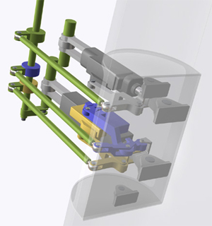
The redesign separates the main PCU "halves," previously housed in the same unit and supplied by both hydraulic systems, into two PCUs, each supplied by a single hydraulic system and operating completely independently. The primary and secondary slides were redesigned by re-spacing the hydraulic ports, in order to prevent the possibility of a reversal should a jam occur, and to prevent the possibility of overtravel of either slide. A pressure limiting system was added to reduce the rudder deflection when not taking off or landing (except for an engine failure at high thrust settings, large rudder deflections are not necessary to control the airplane). To accommodate the segregation of the PCUs, a new torque tube was installed, which incorporates force overrides for each main control rod should either PCU experience a jam. Also, in the event of a jam, the system incorporates (1) a force fight monitor to neutralize the effect of a jam and (2) automatic actuation of the standby rudder system to allow continued operation of the rudder when/if the main PCUs are operating in opposition to each other following a jam in a PCU. Finally, the yaw damper coupler was redesigned to correct a history of problems that had resulted in yaw damper hardovers and yaw damper failures. An illustration of the redesigned PCU configuration, showing the additional redundancies can be seen to the right.
The redesigned system is installed during production of the next generation models of the Model 737 (Model 737-600, -700, -800, -900, and -900ER series airplanes). For fleet models (including the 737NG) built before November 2002, a retrofit program was implemented and will be completed in 2008.
AD 80-07-02, amendment 39-3742 - Conduct a one-time, manual input hardover test on the flight control systems (including the rudder, elevators, and ailerons).
AD 94-01-07, amendment 39-8789 (59 FR 4570, February 1, 1994) - Perform a test of the main rudder PCU to detect internal leakage of hydraulic fluid. Repeat test at intervals of 750 flight hours unless replaced with new main rudder PCU. Superseded by AD 97-14-04 (discussed below).
AD 95-06-53, amendment 39-9199 (60 FR 18981, April 14, 1995 - Compare part and serial numbers of the main rudder PCU with those on a list of suspect parts. If applicable, remove and replace PCU with serviceable part or perform specified testing. Superseded by 2002-20-07 R1 (discussed below).
AD 96-23-51, amendment 39-9818 (61 FR 59317, November 22, 1996) - Perform testing of the main rudder PCU in accordance with Boeing Alert Service Bulletin 737-27A1202. Repeat test at intervals of 250 flight hours unless replaced with new main rudder PCU. Superseded by AD 97-14-04 (discussed below).
AD 96-26-07, amendment 39-9871 (62 FR 15, January 2, 1997) - Revise the airplane flight manual (AFM) to include procedures that would enable the flight crew to take appropriate action to maintain control of the airplane during an uncommanded yaw or roll and correct a jammed/restricted flight control condition. Superseded by AD 2000-22-02 R1.
AD 97-05-10, amendment 39-9954 (62 FR 9679, March 4, 1997) - Remove the main rudder PCU and replace it with a serviceable unit. This was prompted by a report of the installation of an incorrect bolt on the main rudder PCU. The actions specified in this AD were intended to prevent cracking of the bearing of the main rudder PCU due to installation of an incorrect bolt; such cracking could result in seizure of the bearing and resultant uncommanded rudder movement. Superceded by AD 2002-20-07 R1
AD 97-06-09, amendment 39-9966 (62 FR 12739, March 18, 1997) - Replace certain aileron/rudder trim control modules with an improved module that contains a rudder trim switch that precludes the problems of sticking associated with the existing switch. This amendment was prompted by reports of sticking conditions in the rudder trim switch. The actions specified by this AD were intended to prevent such sticking, which could result in uncommanded movement of the rudder and consequent deviation of the airplane from its set course.
AD 97-09-15, amendment 39-10011 (62 FR 24325, May 5, 1997) - Perform a one-time inspection of the engage solenoid valve of the yaw damper to determine the part number of the valve. If the valve part number falls within the range specified, replace the valve with a new one.
AD 97-14-03, amendment 39-10060 (62 FR 34623, June 27, 1997) - Install a newly designed rudder limiting device that reduces the rudder authority during flight conditions for which full rudder authority is not required. Install a newly designed yaw damper system that improves reliability and fault monitoring capability.
AD 97-14-04, amendment 39-10061 (62 FR 35068, June 30, 1997) - Perform all actions required by ADs 94-01-07 and 96-23-51. Replace any main rudder PCU having Boeing part number 65-44861 or 65C37052 with a new main rudder PCU. Replace the vernier control rod bolts having Boeing part number 69-27229 with new bolts. Perform a leak test of the main rudder PCU within 4,000 to 6,000 flight hours of the AD's effective date. Repeat the leak tests at intervals of 6,400 flight hours.
AD 97-26-01, amendment 39-10244 (62 FR 65597, December 15, 1997) - Perform an inspection to detect galling on the input shaft and bearing of the standby rudder PCU within 18 months or 4,500 hours after the AD's effective date, whichever occurs later. Replace the input bearing of the standby rudder PCU with an improved bearing within three years after the AD's effective date.
AD 98-13-12, amendment 39-10600 (63 FR 33246, June 17, 1998) - Perform a one-time inspection to detect discrepancies of the fasteners that connect the pushrods to the rudder pedal assemblies, and corrective actions, if necessary. This amendment was prompted by reports of loose and missing fasteners due to incorrect installation. The actions specified in this AD were intended to prevent loss of rudder control, jamming of the rudder system, uncommanded movement of the rudder system, and consequent reduced controllability of the airplane due to loose or missing fasteners that connect the pushrods to the rudder pedal assemblies.
AD 99-11-05, amendment 39-11175 (64 FR 27905, May 24, 1999) - Perform repetitive displacement tests of the secondary slide in the dual concentric servo valve of the PCU for the rudder, and replacement of the valve assembly with a modified valve assembly, if necessary. This amendment was prompted by reports of cracking found in PCU secondary servo valve slides. The actions specified by this AD were intended to prevent failure of the secondary slide and consequent rudder hardover and reduced controllability of the airplane.
AD 2000-22-02 R1 - Revise the FAA-approved Airplane Flight Manual (AFM) procedure in the existing AD to simplify the instructions for correcting a jammed or restricted flight control condition. This document corrects the format for certain AFM material described in AD 96-26-07 to ensure that the flight crew is aware of certain critical recall items in the AFM procedure that are necessary to address a condition involving a jammed or restricted rudder. The original version of this AD was incorrectly formatted when published in the Federal Register, so the revision was necessary. This AD superseded AD 96-26-07.
AD2002-20-07R1 - Install of a new (redesigned) rudder system within six years of November 12, 2002. This AD was issued prior to a final design being submitted by Boeing and prior to a design approval. It called for installation of a new rudder system "in accordance with a method approved by the Manager, Seattle Aircraft Certification Office (ACO), FAA," and required separate hydraulic inputs, and an override for each, to two separate PCUs, as well as a separate standby actuator with an override. The intended result was a redesigned rudder actuation system that incorporated separate and redundant rudder PCUs and an independent standby PCU. Further, the AD required an override capability such that an unintended command by any one actuator could be mitigated via input to the other actuator, acting in combination with the standby. This AD superseded ADs 95-06-53, 97-05-10, and 98-02-01, amendment 39-10283 (63 FR 1903, January 13, 1998). Superceded by AD 2007-03-07, amendment 39-12940 (67 FR 67518, November 6, 2002.
Airplane Life Cycle:
- Design / Manufacturing
- Operational
Accident Threat Categories:
- Lack of System Isolation / Segregation
- In-flight Upsets
- Incorrect Piloting Technique
Groupings:
- Loss of Control
- Approach and Landing
Accident Common Themes:
- Human Error
- Flawed Assumptions
Human Error
A factor in the accident was an apparent lack of flight crew understanding and/or training relative to exposure to high angles of attack and upset recovery. As the flight path following the upset progressed, the airplane attitude became more nose down, but the angle of attack continued to increase. Early in the event, the pilot pulled the control wheel all the way back, which would result in full up elevator, in an attempt to bring the nose back to a level attitude. This action caused the airplane to stall, and the stall warning system (stick shaker) was activated. The full elevator input was not reduced, and once activated, the stick shaker continued to operate until impact, indicating that the flight crew made no attempt to reduce the angle of attack, or recover from the stall. As previously discussed, an issue to the investigation was the apparent, widespread lack of understanding relative to inflight upset recovery and high angle of attack operation and recovery. This lack of understanding may have been a factor in this particular flight crew unintentionally stalling the airplane and being unable to recover once the stall was fully developed.
Flawed Assumptions
There were at least two flawed assumptions that were contributors to this accident. As discussed earlier, it had been assumed that the Model 737 was always controllable with the rudder fully deflected. Early certification discussions, when addressing the possibility of a rudder hardover or other inadvertent full rudder deflection, concluded that the lateral control system was capable of compensating for the rudder. It was not until this accident that the concept of a "crossover speed" and an area of the flight envelope where the lateral control system could not compensate for a full rudder deflection were fully identified.
It was also assumed, as stated earlier, that a rudder hardover and jam were essentially not possible. While there is still controversy surrounding the NTSB conclusion that the main PCU experienced a secondary slide jam, then primary slide overtravel resulting in a rudder hardover opposite to the direction commanded, there was total reliance on a single valve (powered by both hydraulic systems), such that, if a jam did occur, there was no built-in, automatic or inherent means to alleviate the problem and maintain straight and level flight. In response to this apparent design shortcoming, the FAA mandated a redesign of the rudder system. Boeing's redesign of the rudder system, added a new layer of redundancy, thereby mitigating the possibility of a jam and its consequences.
United Airlines Flight 585
On March 3, 1991, while on approach to Colorado Springs, Colorado, United Airlines Flight 585, a Boeing Model 737-291 airplane, N999UA, rolled to the right and dove into the ground, killing all 25 people on board. The flight from Denver, Colorado had been uneventful, but conditions in the Colorado Springs area were very turbulent with high winds and reported low-level wind shear. The flight crew was concerned about the low-level wind shears, querying the control tower about recent reports. While on final approach, in the landing configuration (flaps at 40 degrees and landing gear down), just after passing through 1,000 feet above the ground, the airplane suddenly rolled to the right. The captain called for 15 degrees of flaps, intending to initiate a go-around. However, control appears to have been lost, and the airplane impacted the ground approximately three miles from the end of the runway.
Initially, the NTSB could not conclusively determine a probable cause of the accident, but determined that the most likely causes were either a weather phenomenon known as a wind rotor, which is common in the area and well known to local sailplane pilots, or a malfunction of the rudder/yaw damper system based on damage to certain parts of the yaw damper and main rudder PCU. The airplane had a recent history of yaw damper anomalies, and maintenance crews had recently replaced the yaw damper coupler. At the time of the accident, the NTSB was not sufficiently familiar with either the rudder system of the Model 737 or with wind rotor phenomena, and was not able to conclude that either event was the cause of the accident. Until USAir Flight 427 and the investigation surrounding that crash, Flight 585 was considered unsolved. Following the investigation into USAir 427, the NTSB, based on information learned from Flight 427, eventually determined that the cause of Flight 585 was also a rudder reversal and subsequent loss of control.
A description of the events of Flight 585 is contained in the NTSB report concerning Flight 427, beginning on page 258. An animation of the flight path of Flight 585 is available below:
Eastwind Airlines Flight 517
While Eastwind Airlines Flight 517 did not crash, it was an important factor in the final outcome of the Flight 427 investigation.
On June 9, 1996, Eastwinds Flight 517, a Boeing Model 737-2H5 airplane, N221US, experienced a roll/yaw upset while in approach to land at Richmond Airport, Richmond, Virginia. The airplane was not damaged, and no one was injured. However, from flight crew interviews and flight data recorder information, the NTSB determined that the airplane had experienced an "uncommanded rudder displacement that exceeded the normal operating limits of the yaw damper system."
At the time of the incident, the airplane was in initial approach at 4,000 feet and approximately 250 knots. The pilot reported afterwards that he had felt a rudder "bump" to the right followed by a roll to the right. He stated that he applied left rudder but the rudder felt stiff. He stated that he used left wheel and asymmetric thrust to control the airplane. Upon accomplishment of the emergency checklist, when the yaw damper was turned off, the airplane became controllable, but the flight crew wasn't sure if the problem corrected itself coincident with yaw damper deactivation. The airplane had a previous history of rudder "bumps" and difficulty in trimming. The main rudder PCU had been replaced on May 14, 1996, approximately three weeks before the incident. NTSB examination of rudder components determined that the yaw damper linear variable displacement transducer (LVDT) was misadjusted such that rather than allowing a three-degree displacement in both directions, would cause a displacement of only 1.5 degrees to the left and 4.5 degrees to the right with no aerodynamic loads on the rudder. Simply stated, the yaw damper would deflect the rudder asymmetrically. The NTSB also discovered chafed wiring between the yaw damper coupler and the main rudder PCU, which they determined could have resulted in a short circuit and a yaw damper hardover (which in this case would result in a rudder deflection to the right, beyond the normal limits of the yaw damper's capability). A kinematic analysis of the flight data recorder information determined that the rudder required to create the resultant flight path was at least six degrees, which was beyond the capability of the misadjusted yaw damper LVDT.
Based on the results of flight crew interviews, kinematic analyses, and computer simulation data, the NTSB determined that the event experienced by Eastwind Flight 517 was a rudder reversal, initiated when the pilot pushed on the left rudder pedal, resulting in a roll to the right. The event had been controllable because of the airplane's relatively high speed (well above the crossover speed).
A more complete description of the Eastwind incident is contained in the NTSB report concerning Flight 427, beginning on page 263. An animation of the incident flight path is available below:
Technical Related Lessons:
A non-redundant flight control actuator such that all hydraulic systems are ported to a single (split) actuator, may be subject to a single-point failure, that can result in uncommanded, perhaps reversed, motion. (Threat Category: Lack of System Isolation/Segregation)
- While the single PCU provided redundant hydraulic flows in the event of a hydraulic failure, the NTSB concluded that it was susceptible to a single failure (secondary slide jam) that could affect both hydraulic flow paths and result in a rudder reversal. A redesign of the rudder system of the Boeing Model 737 was necessary to eliminate this hazard.
Stall recovery procedures should be initiated immediately when airplane stall warning is encountered. (Threat Category: Incorrect Piloting Technique)
- Early in the upset, the pilot flying applied full nose-up elevator, rapidly resulting in an airplane stall. The stall warning system functioned properly, but the flight crew did not respond, and maintained the stall condition until ground impact. It is essential that certain types of warning annunciations, such as stall warning, result in an immediate, and proper, response from the flight crew.
Prescribed operational speeds should be sufficiently above "crossover" speeds (where yaw authority overcomes roll authority) that operational envelopes do not expose a potential loss of control. (Threat Category: Inflight Upsets)
- Prior to this accident, while the concept of crossover - the idea that the lateral and directional control systems are not balanced in their authority - was not unknown, it was believed that crossover occurred below stall speed, and therefore would not be a factor operationally. This accident highlighted the critical nature of crossover, and the operational overlaps (prescribed operational speeds at or below crossover speeds), and the need to mitigate or eliminate operational exposure to crossover effects.
Flight crew reaction to inflight upsets could be improved by special recognition and recovery training. (Threat Category: Inflight Upsets)
- In this accident, the flight crew response to the upset was deemed to have been inappropriate. The crew was clearly startled by the event and did not immediately recognize what was occurring. Their response to the resulting unusual attitude was to apply full nose-up elevator in an attempt to raise the nose toward the horizon. The application of full nose-up elevator resulted in the airplane remaining fully stalled. Had this crew been more thoroughly trained in upset recognition and recovery techniques, especially from high angles of attack, a prompt recovery from the stall may have been possible.
Common Theme Related Lessons
High angles of attack, and airplane stall, are achievable in attitudes not normally associated with stall conditions. Crew response to a stall warning should be consistent, irrespective of perceived airplane attitudes. (Common Theme: Human Error)
- The possible lack of understanding among operational flight crews related to high angles of attack and the possibility of stalling when operating above published stall speeds and in "nose low" attitudes, resulted in the development of the Upset Recovery Training Aid. The CVR provided ample evidence that the flight crew did not understand that, even though the airplane attitude was "nose low"-not normally indicative of a high angle of attack-the airplane was stalled and required a reduction of angle of attack to allow recovery. The Upset Recovery Training Aid was a step in explaining high angle of attack phenomena and provided a means for carriers to develop their own training programs for recovery from high angle of attack and flight path upset situations.