


Enstrom 280FX
New Course Aviation Company, N86235
Erie, Colorado
January 26, 2015
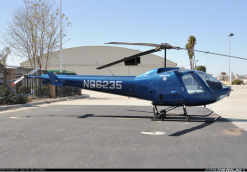
On January 26, 2015, about 1202 mountain standard time (MST), an Enstrom 280FX, N86235, was destroyed when it impacted terrain during final approach for landing at Erie Municipal Airport (EIK), Erie, Colorado. Both the instructor pilot and student pilot were fatally injured.
The helicopter was registered to New Course Aviation Company and operated by Mountain One Helicopters as a 14 Code of Federal Regulations (CFR) Part 91 instructional flight. Visual meteorological conditions prevailed for the local flight, which operated without a flight plan.
The National Transportation Safety Board (NTSB) determined the probable cause of this accident was an in-flight failure of the helicopter's No. 2 main rotor spindle due to undetected fatigue cracking. This condition resulted in the loss of the blade and subsequently, an in-flight breakup. Contributing to the failure was the spindle’s nonconforming thread root radius. The manufacturer also failed to include a bending moment within the spindle threads when performing the fatigue analysis during the spindle’s initial design.
NTSB report: CEN15FA126
History of Flight
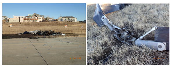
During an instructional flight with a student pilot and flight instructor on board, the No. 2 blade separated from the main rotor head. The rotor head and transmission separated next, and the helicopter descended and impacted the ground. The student and instructor were fatally injured and a post-crash fire destroyed the helicopter.
According to an NTSB witness interview, the helicopter was on final approach to land on the runway at what seemed like a steep angle of descent. As the helicopter descended, the witness heard a loud "pop." After the pop, the helicopter fuselage began to rotate and then the main rotor (MR) blades separated from the top of the helicopter. The remainder of the helicopter descended to ground impact.
During the scene investigation, the No. 2 blade was found separated, while No. 1 and No. 3 were still attached to the rotor head. Further examination would determine that the No. 2 blade had separated because of a fractured spindle.
Enstrom 280FX Information
The helicopter, an Enstrom 280FX, was a three-seat, single-engine helicopter (serial number 2002) manufactured in 1985. The three-bladed MR system is driven through a main gearbox powered by a turbo-charged Lycoming HIO360-F1AD engine. The inboard end of each MR blade is attached to its respective grip and drag link. Each rotor blade is attached to the outboard side of its respective grip via a retention bolt. At the inboard side of each grip, a pitch arm and drag link are attached to the leading and trailing sides, respectively, of the grip. Two feather bearings, which accommodate rotor blade pitch change motion, a bearing spacer, and a spindle are installed within the grip. A Lamiflex bearing, a spindle retention nut, and a cover are installed at the threaded outboard end of the spindle. Two flanges at the inboard end of the spindle attach to a universal block, which is attached to the main rotor hub, allowing for rotor blade flapping and lead-lag motions.
Spindle Design
This following animation explains the location, function, and failure of the spindle.
The spindle is a critical component in a rotorcraft’s rotor system. It secures the blade grip assembly as it rotates around the hub. The end of the spindle has threads which hold a Lamiflex bearing, retention nut, and cover.
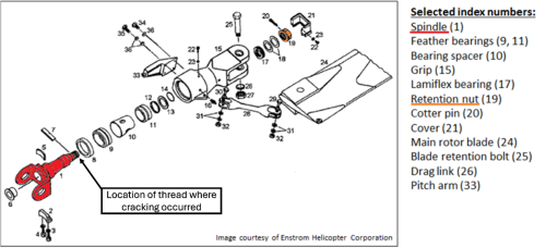
In the accident, the spindle cracked at the location of the threads. Most of the spindle remained connected to the main rotor hub, but the spindle’s threaded portion, as well as the blade, grip, retention nut, and drag link separated from the hub.
These threads are only visible after removing the retention nut for the Lamiflex bearing. All three bearings had been replaced multiple times since manufacture, with the most recent replacement being on March 17, 2014 (nine months before the accident). This is the last time that any wear, damage, or cracking may have been visible on the spindles before the crash. However, an inspection of the threads was not required, and any wear or damage was likely too small to be noticed visually without the use of a magnetic particle inspection.


In reviewing the spindle’s design at the location of the break, investigators found that the design was based on an incorrect assumption: the axial centrifugal force due to blade rotation was the only significant load acting on the spindle. However, an Enstrom test after the accident confirmed the presence of a bending moment that increased stress at the location of the break.
To quantify the increase in stress, the NTSB developed a 3-D finite element (FE) model of the spindle, which calculated that bending moments increased the stress in the threaded location by 14 percent.
Manufacturing Flaw
The NTSB Materials Lab examined the broken spindle and determined that the average root radius of the threads was smaller than specified by the Enstrom design drawing. The root radius is the radius of the curve at the bottom (or root) of the thread. The average root radius of the broken spindle was 0.00459 inches, about half of the specified radius of 0.009 inches. Furthermore, the threads on the spindle that failed had flat roots instead of the specified rounded roots.

To determine the significance of this difference, the NTSB modeled both thread profiles under different combinations of axial stress and bending moments. It was found that the stress on the thread was doubled in the measured profile.

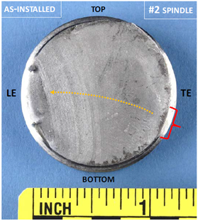
All three spindles had significant cracking as well as signs of corrosion, indicating that the crack that ultimately caused the failure had been growing for a long time. 92 percent of the cross section of the broken (No. 2) spindle had cracked over time before the accident, with the remaining 8 percent failing from overload at the initiation of the accident sequence.
Conclusion
The rotorcraft crashed after a sudden failure of the spindle, which led to the separation of the rotor blade and an in-flight breakup. The spindle failed because of undetected fatigue cracking, which was caused by a combination of incorrect design assumptions and manufacturing errors.
The spindle design did not account for a bending moment. After the accident, Enstrom conducted physical testing which confirmed the existence of a bending moment. More significantly, all three spindles on the rotorcraft had thread roots that were smaller than the specification in the drawing. In combination, these two factors made the spindles substantially more vulnerable to fatigue cracking under conditions that were well below the part’s intended structural capability.
The NTSB determined the probable cause of the accident to be the in-flight failure of the helicopter's No. 2 main rotor spindle due to undetected fatigue cracking, which resulted in an in-flight breakup. Contributing to failure was the spindle’s nonconforming thread root radius. The manufacturer also failed to include a bending moment within the spindle threads when performing the fatigue analysis during the spindle’s initial design.
NTSB report: CEN15FA126
The following regulations were in place in 1985, when the Enstrom 280FX was certified and when the accident helicopter was manufactured. They have been included because of their relevance to the design and quality issues which caused the accident to occur. Commentary is given in italics to distinguish it from the regulatory text:
14 CFR § 21.165 – Responsibility of holder
Amendment Number: Initial, Effective Date: 02/01/1965
The three spindles installed on the aircraft did not conform to the type design. This regulation requires that the production certificate holder determine that each completed product conforms to the type design.
14 CFR §27.301 Loads
Amendment Number: Initial, Effective Date: 02/01/1965
This regulation requires design conditions to approximate real-world loading. The bending moment was a component of loading which was not fully accounted for in the spindle’s design.
14 CFR §27.307 Proof of structure
Amendment Number: 27-3, Effective Date: 10/17/1968
After the accident, the presence of a bending moment was confirmed through physical load testing. Physical testing during the design process may have allowed for its identification and measurement prior to the accident.
Enstrom 280FX, Private Pilot, Thruxton, England, September 30, 1991

Photographer: Alec Wilson, use permitted under license CC BY-SA 2.0
On return to the airfield, the pilot felt the rotorcraft vibrating, followed by a loud bang. The aircraft yawed to the right with the yaw pedals seized. The pilot entered autorotation and forced a landing in a field. They discovered that the tail rotor gearbox casing had separated into two pieces, disconnecting the input gear and damaging the rotor guard and control cables. The tail rotor spindle was also fractured, but fortunately not in a way which disconnected the rotor. A metallurgical examination determined that the spindle had surface discontinuities and/or flaking, caused by poor shot-peening in the manufacturing of the part.
Three years before the 1991 accident, Enstrom had issued Service Bulletin 0077 to visually inspect the tail rotor spindle, conduct a dye-penetrant crack check, and repeat checks at 100-hour intervals. The CAA and FAA did not make the bulletin mandatory until after the accident.
Four days after the accident, the CAA issued Emergency Airworthiness Directive 001-10-91 to mandate the initial inspection. Bulletin 0077 was revised in 1992 to include a life limit of 1200 hours for the specific part numbers N 28-150064-11 and -13. In addition, a new part, 28-150074, was developed as a replacement for the life limited parts. In 1994, the FAA adopted AD 94-13-03 to make the service bulletin mandatory.
This incident involved a tail rotor spindle, which is different than the main rotor spindle that failed in the 2015 accident. However, both events involved a spindle with no life limits or inspection requirements for fatigue fracturing. The failure of one type of spindle is not necessarily a precursor for another, but had the 1991 incident led to a reassessment of spindle life limits and inspection requirements, the 2015 accident may have been prevented.
The bending moment was not included in the analysis of the loads used to design the spindle. The NTSB investigation determined that this omission was because Enstrom considered the bending moment to be insignificant relative to the larger centrifugal force.
In addition, the treatment of the spindle as a part without life limits or inspection requirements virtually eliminated the chance of the cracking being identified prior to failure.
Most significantly to the accident, the spindle threads were not manufactured in conformance with the design drawings, which made them vulnerable to fatigue and cracking. The spindles threads required a rounded root profile with a wider root radius as compared to the manufactured narrow, flat profile.
Inadequate spindle design
- Designers assumed that the only significant force on the spindle would be the centrifugal force of the blades rotating. This resulted in a spindle designed for lower stress. After the accident, Enstrom measured the bending moment, which increased thread stress by 14 percent.
Manufactured parts did not conform to the design
- After the accident, all three spindles, including the one which failed, were examined. The NTSB discovered that the thread root radius of all three spindles was smaller than specified in the design. This change resulted in a 100 percent stress increase at the location on the thread that failed.
Parts are designed and tested for realistic loading conditions to ensure that they do not fail during operation.
- The structural analysis of the spindle design did not account for a bending moment which significantly increased stress. This bending moment was identified after the accident through physical testing, and if the same physical testing had been done during the design process, this assumption might have been disproved.
Parts installed on an aircraft are in conformance with the type design.
- All three spindles installed on the accident aircraft had a nonconforming thread root radius which effectively doubled the stress on the designed part. The quality control system in place was not sufficient to identify these nonconformities prior to installation.
Scheduled maintenance inspections will identify signs of part wear and damage prior to failure.
The spindle was not categorized as a life-limited part, and so the thread where the fracture occurred had not been inspected prior to the accident.
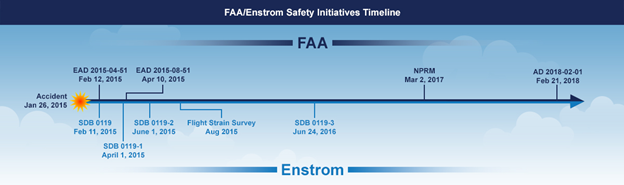
Once the cracked spindle had been identified as the cause of the accident, a series of actions occurred to identify and remove all cracked spindles in the fleet. As more information was collected on the extent of the cracking, inspection requirements were established to prevent spindles from reaching a dangerous degree of cracking in the future.
In the paragraphs below, actions taken by Enstrom and the FAA are listed separately, but these actions were closely connected, with the immediate goal of identifying the scope of the safety issue and the long-term goal of preventing similar accidents.
Enstrom Actions
On February 11, 2015, Enstrom Helicopter Corporation (Enstrom) issued Service Directive Bulletin (SDB) No. 0119, that required a magnetic particle inspection (MPI) for MR spindles, P/N 28-14282-11 and 28-14282-13, that were in service more than 5,000 hours. The bulletin specified that the MPI should be completed within the next five hours of time-in-service (TIS). For MR spindles with less than 5,000 hours TIS, the spindle should be removed and sent to Enstrom for MPI at or before 5,000 hours TIS. The SDB also specified a repetitive MPI conducted every 300 hours after the initial 5,000 hour TIS.
Based on the findings of the MPI tests conducted after the issuance of Enstrom's initial SDB, Enstrom issued a revised SDB (Revision 1) on April 1, 2015. The revision reduced the TIS before an MPI was required from 5,000 hours to 3,500 hours. On June 1, 2015, Enstrom issued Revision 2 to the SDB further reducing the TIS before an MPI was required from 3,500 hours to 1,500 hours.
In August 2015, Enstrom conducted a flight strain survey to characterize the loads placed on the P/N 28-14282-13 spindles during normal and abnormal flight conditions to determine whether bending loads existed at the spindle threads. The strain survey revealed a bending moment that was not accounted for in the original spindle analysis.
Additionally, Enstrom performed a crack growth analysis to evaluate cracks about the cotter pin hole. At the time of the analysis, less than 6 percent of the overall spindles returned from the field exhibited cracks in the cotter pin hole (much less than the approximately 20 percent recorded when the FAA EAD 2015-04-51 was first released). Other than two spindles from the accident aircraft, no additional spindles were found to exhibit cracks about the inboard threaded region of the spindle. As a result of the analysis, on June 24, 2016, Enstrom issued Revision 3 to the SDB. This revision modified the original 300-hour repetitive MPI requirement to a 500-hour interval repetitive MPI after the initial MPI at 1,500 hours TIS.
On February 12, 2015, the FAA issued Emergency Airworthiness Directive (EAD) 2015-04-51 requiring that any spindle with 5,000 hours or more TIS, or where the hours TIS of the spindle was not known, have an MPI before further flight to determine if a crack exists. If a crack in the spindle was found, the EAD required replacing the spindle before further flight. The EAD further required that MPI testing results for all spindles be reported to the FAA.
On April 10, 2015, the FAA superseded EAD 2015-04-51 with EAD 2015-08-51 which advised that, based on inspection reports that the FAA received, about 20 percent of the spindles that were MPI tested had evidence of cracks. As such, the FAA expanded the applicability of spindles requiring testing to those with 1,500 or more hours TIS.
On March 2, 2017, the Federal Register published a notice of proposed rulemaking (NPRM) to issue an AD for Enstrom MR spindles (P/N 28-14282-11 or 28-14282-13) to establish a life limit of 1,500 hours TIS and require a recurring inspection interval of 500 hours until the spindle reached its new life limit of 1,500 hours TIS. AD 2018-02-01, effective February 21, 2018, mandated the requirements proposed in the NPRM.
With the publication of AD 2018-02-01, this safety issue was considered resolved. With mandatory inspections every 500 hours and a spindle life limit of 1500 hours, cracking of the spindle can be identified well before it progresses to the point of failure, and spindles are regularly replaced instead of being left in service indefinitely.
Rotorcraft Life Cycle
- Design/Manufacturing
Accident Threats
- System / Component Failure or Malfunction (non-powerplant) (SCF–NP)
Industries
- Instructional/Training
Accident Common Themes
- Organizational Lapses
- Flawed Assumptions
Flawed Assumptions
- The structural analysis for the spindle design assumed the only significant loading on the spindle was longitudinal (centrifugal). Physical testing after the accident identified a significant bending moment on the spindle.
Organizational Lapses
The quality control system in place did not prevent multiple nonconforming parts from being put into service.
Bell 212, Yellowhead Helicopters, Evansburg, Alberta, June 28, 2021
The following accident did not occur on an Enstrom 280FX or involve a cracked spindle. However, it gives insight into one of the key issues in the Enstrom accident- how a nonconforming part can be put into service despite quality checks and procedures:

During firefighting operations, a Bell 212 C-GYHG experienced an in-flight breakup in which two blades separated from the main rotor assembly, causing the helicopter to crash. The pilot, who was the only person on board, was fatally injured. Investigators with the Transportation Safety Board of Canada (TSB) found that the main rotor hub strap retaining pin on blade A had broken, leading to the first blade separation and loss of control. The pin in question had been replaced eight days earlier because of a requirement to replace the rotor hub straps every 1,200 flight hours or 24 months.
Analysis of the broken pin determined that it was made with SS216 stainless steel, while the other three pins were made with H11 tool steel. Tool steel has greater toughness and resistance to fatigue, and was the material specified by the engineering drawings. These pins were subcontracted by Bell to Fore Machine Company (FMC).
While examining the manufacturing processes at FMC, investigators discovered that the rods used to make the pins were stored by diameter, not material, meaning workers could accidentally select the wrong material. Furthermore, the quality control inspectors at FMC allowed less trained assistants to conduct hardness tests, a multi-step process where instructions needed to be followed exactly to obtain accurate readings. Because of these two issues, the pins made of the wrong material were not identified before sending them off for heat treatment.
The quality issue was identified by Bodycote, a different subcontractor who had heat treated the pins and found inconsistent hardness measurements. Forty-four nonconforming pins were marked and returned to FMC in a separate box from the pins which met the hardness requirements. Bodycote also emailed FMC and informed them of the issue, but the employees at FMC who received the email did not inform the inspector who was assigned to process the pins, and so the defective batch was not removed from production. After several additional stages of production and QC inspections, 131 pins were sent to Bell by FMC, including 12 pins made from the wrong type of steel. The pin involved in the fatal accident was one of those pins.
In summary, the TSB determined that the cause of the accident was the failure of the rotor hub strap retaining pin, which was made with the incorrect type of steel. Proper material storage and quality control practices would likely have prevented the nonconforming part from being delivered to Bell.

TSB Report: A21W0045
Technical Related Lessons
Once a nonconforming part enters service, the ability to detect that nonconformance before failure is low. (Threat Category: System/Component Failure Non-Powerplant)
- To avoid the release of nonconforming parts, the quality control process must ensure that parts are manufactured and inspected to conform with the approved type design. Scheduled inspections prescribed by the Instructions for Continued Airworthiness (ICA) are intended to identify signs of damage, fatigue, or corrosion in a correctly manufactured part, not to verify conformity with the part design.
- All three spindles installed on the accident rotorcraft had nonconforming thread root radii. The nonconformance was estimated to double the stress at the point of failure. This stress increase led to potential for crack initiation and subsequent growth across the spindle. This would have been undetectable without testing, such as magnetic particle inspection (for which there was no requirement).
Common Theme Related Lessons
During the design process, it is important to validate assumptions that impact the performance of critical parts. (Common Theme: Flawed Assumptions)
- Assumptions are a necessary part of the design process. Building and testing every component in every configuration is impractical. However, if an assumption can have a significant impact on the safe operation of an aircraft, validate that assumption through risk analysis or physical testing to see if the assumption is correct.
- For the aircraft involved in this accident, the design was based on the assumption that the only significant load on the spindle would be centrifugal forces, and did not account for bending moments in the structural analysis.
- After the accident, physical testing by the manufacturer demonstrated that a significant bending moment did exist. NTSB modeling estimated the moment to increase thread stress by 14 percent, which could contribute to crack initiation and growth across the spindle.