
Eurocopter AS350B2
Sundance Helicopters, N37SH
Las Vegas, Nevada
December 7, 2011
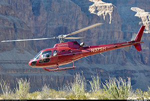
Source: Sergey Rimsha
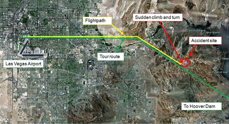
On December 7, 2011, at approximately 1630 PST, a Eurocopter AS350B2 helicopter operated by Sundance Helicopters, Inc. crashed in mountainous terrain about 14 miles east of Las Vegas, Nevada. The pilot and four passengers were fatally injured; impact forces and post-impact fire destroyed the helicopter. This was a tourist sightseeing flight which departed from Las Vegas McCarran International Airport (LAS), intending to fly to the Hoover Dam area and return to LAS, operating under visual flight rules. This was the fourth flight of the day.
The NTSB determined the probable cause of this accident was Sundance Helicopters' inadequate maintenance of the helicopter. This included (1) the improper reuse of a degraded self-locking nut, (2) the improper or lack of installation of a split pin, and (3) inadequate post-maintenance inspections. The improper maintenance resulted in the in-flight separation of the servo control input rod from the fore/aft servo and rendered the helicopter uncontrollable. Contributing to the improper or lack of installation of the fastener (self-locking nut and split pin) was the mechanic’s fatigue and the operator's lack of clearly delineated maintenance task steps to follow, which also led to the inadequate post-maintenance inspection.
NTSB Number: DCA12MA020
History of Flight
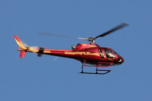
Source: Kev Colbran
The AS350B2 was registered to and operated by Sundance Helicopter Inc. The company utilized the helicopter for air tour flights under the provisions of 14 Code of Federal Regulations (CFR) Part 135. Visual meteorological conditions with good visibility were present at the time of accident. The flight departed under visual flight rules from Las Vegas McCarran International Airport (LAS), Las Vegas, NV for a tourist sightseeing flight to the Hoover Dam area.
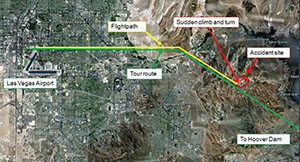
FAA radar data showed the helicopter followed the prescribed Twilight Tour route easterly from the airport traffic area. It then turned southeast toward the Hoover Dam where the helicopter was level at 3,500 feet mean sea level (MSL) at a groundspeed of about 120 knots. About one minute before impact, radar data showed the helicopter climbed to 4,100 feet MSL, turned about 90 degrees to the left, and then slowed after the turn (the climb and left turn were not part of the Twilight Tour flight route). The helicopter then descended to 3,300 feet MSL according to radar data and tracked a northeasterly course for about 20 seconds. It then entered a left turn and descended at a rate of at least 2,500 feet per minute until impact. The last radar target was about 1/8 mile from the accident site.
Accident Site
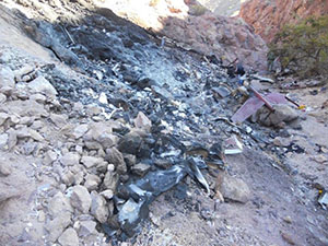
Source: NTSB
View Larger
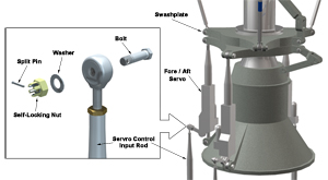
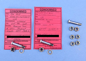
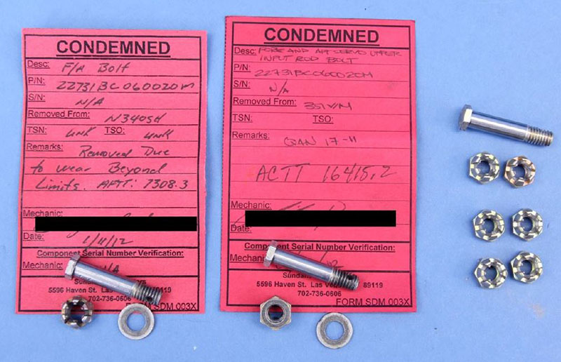
The helicopter impacted terrain in a nose-low attitude on an approximate north-easterly heading. The cockpit area and fuselage were found in the immediate wreckage area, but a large percentage of the fuselage in front of the horizontal stabilizer was consumed by post-impact fire. Examination of the wreckage revealed the fore/aft rotor servo was not connected to the input rod. Investigators were unable to find the bolt, washer, self-locking nut, and split pin (sometimes referred to as a "cotter pin" or "cotter key"). The investigation revealed the hardware was improperly secured during maintenance that was conducted the day before the accident. During flight, the nut became loose. Without having been properly torqued and with the absence of a split pin to secure it, the nut came off the bolt. The bolt then separated from the linkage, which allowed the input rod to disconnect from the servo. As a result, the helicopter became uncontrollable and crashed.
Source: NTSB
The main rotor transmission area of the helicopter is not sealed; thus, the compartment does not retain the hardware if separated. The control input rods for both main rotor lateral servos and the tail rotor servo were found properly connected to their respective servo input levers. The fore/aft servo's control input rod was found in two pieces. One piece was a 14-inch section of the upper input rod end that was found disconnected from the fore/aft servo input lever. The other piece was a three-inch section of the lower end of the input tube which was found correctly attached to its linkage. Examination of the 14-inch section of the upper input rod-end revealed no visible elongation of the bolt hole. The separation points on both sections of the input rod were consistent with overload/impact damage.
Servo System Description
View Larger
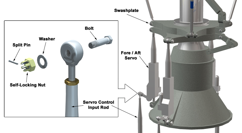
The Eurocopter AS350B2 helicopter is equipped with a single three- bladed main rotor system. The flight control system is a mechanical flight system assisted by hydraulic actuators. Cyclic and collective controls are mechanically routed to a transmission-mounted hydraulic servo control system, which controls lateral, longitudinal, and collective control. Control inputs are transferred to the helicopter's main rotor system via control rods interconnected by bellcranks and levers. The control linkages are routed beneath the main cabin and aft to the mixing unit. Pilot movements of the collective and cyclic controls are transferred to the mixing unit, which apportions the commands through the appropriate servo control input rod to a servo input rod assembly.
Rotor servos have three connections. One connection is at the lower end of the servo and fixed to the main rotor transmission case. Another connection is at the upper end of the servo and secured to the nonrotating swashplate. The third connection is the servo control input rod, which supplies pilot commands to extend or retract the servo. NTSB laboratory microscopic examinations of the fore/aft servo's attachment area verified the fastener was not present at the time of impact. Note: Investigators were not able to determine with certainty if the fastener was installed correctly.
This animation describes servo operations and fastener devices:
Fore/Aft-Servo Maintenance
Self-locking and Anti-rotation Fasteners
Because of the high-vibratory environment of most rotorcraft, manufacturers have found it useful to determine if and where self-locking fasteners are needed during rotorcraft design. Once a fastener is selected, maintenance programs are developed to ensure proper installation and inspections are accomplished.
Certain types of fasteners have locking features or anti-rotation qualities that reduce the likelihood of coming off when subjected to vibrations and other conditions during flight. These features often include Teflon or plastic inserts that use high-rotational forces for installation. Below are some examples of self-locking and anti-rotation fasteners commonly used in rotorcraft design:
Self-locking and Anti-rotation Fasteners
| Sundance AS350 Fore/Aft servo fastener | In some rotorcraft flight control installations, a fail-safe or backup design approach may not be employed for methods used to connect flight-critical components. The hardware used for connecting the servo control input rod to the fore/aft servo on the AS350 is a good example, where a single malfunction or failure of the connecting hardware caused the loss of control and the accident. While the nuts used in this installation are of a dual locking design (castellated nut with elastic integral insert material), they do not have the benefit of fail-safe or backup features. Thus, the installation of components during maintenance and inspection activities is critical to ensure proper control system operation. | 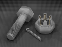 |
| Self-locking nuts | Self-locking nuts have an integral feature that provide friction to the threads of a bolt to prevent loosening; an elastic material such as nylon or fiber is often used. The fiber or nylon locking material is not threaded; friction of the bolt threads against the elastic material causes it to compress, resulting in resistance. | 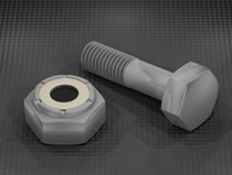 |
| Castellated nuts | A castellated nut is a locking device that is resistant to rotational forces and vibration. It can be readily removed. Castellated nuts are formed with a round section at the top where slots are located, and they are designed to use a cotter or split pin that fits through the slots and through a bolt hole. Castellated nuts are typically used in low-torque applications. Some castellated nuts also have integral elastic inserts used in self-locking nuts. | 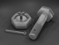 |
| Thread locking fluids | Thread-locking fluid is a thin adhesive applied to the threads of fasteners to prevent loosening. It can be permanent or removable. Typically, fluids are color-coded to indicate strength and whether they can be removed easily or if they require heat for removal. | 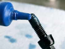 |
| Lock washers | Lock washers are placed beneath fasteners. Lock washers exert a spring tension that keeps the fastener from vibrating loose and are often attached to the nut side of the fastener. Lock washers are made from such hardened metals as stainless steel, galvanized steel, zinc-plated steel, and silicone bronze. | 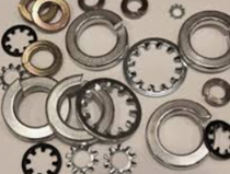 |
| Torque-to-spec | Torque refers to the amount of rotational force applied to the nut. It is used to create tension or clamping force to secure a bolt and nut. The amount of torque applied is a function of frictional forces and bolt diameter. A common application of torque-to-spec fasteners is lug nuts on an automobile wheel. | 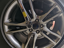 |
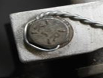
| Safety wire | Safety wire is a type of positive retention locking device that prevents fasteners from rotation and becoming loose due to vibration and other forces. The presence of safety wire may also serve to indicate that the fasteners have been properly tightened. Witness marks (usually a small dab of paint) are often placed on the bolt to show that a mechanic has completed installation to the proper torque or used as visual indication that the nut has not counter-rotated. |
|
Source: NTSB
View Larger
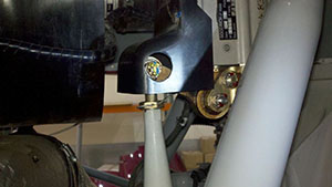
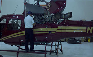
A day prior to the accident, mechanics performed several maintenance tasks. They completed a 100-hour inspection and replaced the tail rotor servo, the engine, and the main rotor fore/aft servo unit. The fore/aft servo installation includes an ice shield which is attached to the top of the servo and has a cutout for viewing the nut and split pin of the input lever connection when the left main gearbox cowl is opened for access. During replacement of the fore/aft servo, the mechanic stated he replaced the servo’s upper rod end, torqued and safetied everything (including securing the input rod connection with a split pin). He connected hydraulic lines and re-torqued all the rod ends. He also stated he did not encounter any difficulties during the installation. The mechanic explained that when he determined whether a nut could be reused, he would remove, clean, and then visually inspect it for cracks, damage, or discoloration. He would then thread the nut on the bolt to see if it would thread all the way down. If he was able to turn the nut down to where the shank was visible, he would replace the nut. In the case of the accident helicopter, he determined the hardware was reusable. No documents required the mechanic to verify completed steps nor record critical parameters such as torque values.
Post Maintenance Inspection

Source: Airbus
View Larger
The inspector reported, when inspecting fore/aft servo installations, he looks for "the two safeties on both the rod ends, the two split pins on the mount hardware, and the safety holding the two bolts that hold the accumulator assembly to the servo." He specifically stated "he inspected the fore/aft servo input rod, hardware, and split pin; marked them with a torque pen; and inspected hydraulic lines that connect to the manifold." When asked when or if hardware could be reused, the inspector responded that Eurocopter Standard Practices Manual provides guidance. He reported that based on his personal experience, if the nut can be threaded all the way on by hand, it cannot be reused because it has lost its entire locking feature.
Parts Reuse Guidance
Source: NTSB
View Larger
The investigation revealed Sundance Helicopters' maintenance personnel were reusing nuts that did not meet the criteria specified by Eurocopter or FAA guidance. Eurocopter requires replacement of the bolt if the nut does not meet torque limits. In addition, Advisory Circular 43.13-1B, "Acceptable Methods, Techniques, and Practices-Aircraft Inspection and Repair," section 7- 64, "Self-Locking Nuts," states, "After the nut has been tightened, make sure the bolt or stud has at least one thread showing past the nut. DO NOT reuse a fiber or nylon lock nut if the nut cannot meet the minimum prevailing torque values."
Even if the bolt and nut were improperly torqued or the nut was degraded, the split pin should have prevented loss of the nut. With the pin installed properly, the self-locking nut can only be removed with high torque shearing of the pin; however, according to the accident report, it is highly improbable this occurred because the magnitude and direction of the forces needed to shear the pin were not present during controlled operation or normal vibrational loading. However, if the split pin was installed without properly spreading the tangs, the pin can fall out with little effort.
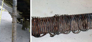
Following the accident, Sundance Helicopters' mechanics inspected all company AS350 helicopters to ensure the fore/aft servo hardware were properly connected. All fore/aft servos were found properly connected with split pins. Additionally, the connection hardware for each of the three main rotor servos on all company helicopters which had 5,000 or more total flight hours was removed and examined. About half of the self-locking nuts from the 13 helicopters examined had no locking capability (i.e., self-locking feature was inadequate), and about half of the bolts had wear markings on the shanks. Examinations of the bolts could not determine where the markings on the bolt shanks originated. Sundance Helicopters provided the NTSB with self-locking nuts from two of the examined helicopters. Both nuts could be easily and fully tightened or loosened on their accompanying bolts with finger pressure. This indicated that the nuts from the two helicopters were not suitable for reuse because new nuts restrict movement by hand after two to three turns. In addition, torque measurements found the turning resistance was about one-inch pound force or less in both directions; Eurocopter recommends 18- to 61-inch pound force.
Flights After Maintenance
Source: NTSB
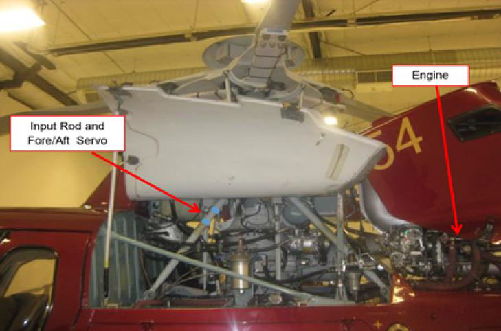
On the day of the accident, two Sundance pilots flew the accident helicopter on four separate flights. The first flight was a Post Maintenance Operational Flight Check. During this check, the pilot’s preflight inspection revealed the belt tension for the hydraulic pump required tightening. The inspection did not note any other issues. The fore/aft servo input rod connection hardware is about eye level for a pilot inspecting the left Main Gear Box (MGB) area when the left main gearbox cowl is opened for access. After adjustment of the hydraulic belt tension, the pilot continued the Post Maintenance Operational Flight Check. All temperatures and pressures were within parameters, hydraulic checks were normal, and the engine passed its power check. The entire Post Maintenance Operational Flight Check was 0.2 hours on the engine run time meter. The same pilot inspected the helicopter after the Post Maintenance Operational Flight Check and found no issues.
The second flight was conducted by the same flight check pilot and was a tour flight that departed at 0945 to the Grand Canyon. The tour included a landing and shut down at the bottom of the canyon. During this flight of about 1.4 hours on the time meter, the aircraft performed normally and the pilot did not note anything out of the ordinary.
The third flight was conducted by the accident pilot at approximately 1330. The flight returned at 1537. As with the previous flight, the aircraft performed normally and nothing was out of the ordinary.
The fourth and final flight departed at 1621 and had no reported issues at takeoff. At approximately 1630, the aircraft began to experience an in-flight loss of control and crashed in the rocky canyons 14 miles from its takeoff point.
Conclusion
Investigators could not determine the specific sequence of events that led to the maintenance error(s). However, investigators determined that regarding proper installation of self-locking nut or split pin, the mechanic did not perform a step or did not perform it properly. Whether the error involved the mechanic not properly securing the hardware and/or the inspector not properly checking the hardware installation, the maintenance program failed to prevent or detect the error.
The National Transportation Safety Board determined the probable cause of this accident to be Sundance Helicopters’ inadequate maintenance of the helicopter, including:
- Improper reuse of a degraded self-locking nut
- Improper or lack of installation of a split pin
- Inadequate post maintenance inspections
NTSB Report Number: DCA12MA020
Key NTSB recommendations to the FAA:
As a result of this investigation, the NTSB issued three recommendations to the Federal Aviation Administration (FAA):
A-13-01
Establish duty-time regulations for maintenance personnel working under 14 Code of Federal Regulations Parts 121, 135, 145, and 91 Subpart K that take into consideration factors such as start time, workload, shift changes, circadian rhythms, adequate rest time, and other factors shown by recent research, scientific evidence, and current industry experience to affect maintenance crew alertness.
A-13-02
Encourage operators and manufacturers to develop and implement best practices for conducting maintenance under 14 Code of Federal Regulations Parts 135 and 91 Subpart K, including, but not limited to, the use of work cards for maintenance tasks, especially those involving safety-critical functions, that promote the recording and verification of delineated steps in the task that, if improperly completed, could lead to a loss of control.
A-13-03
Require that personnel performing maintenance or inspections under 14 Code of Federal Regulations Parts 121, 135, 145, and 91 Subpart K receive initial and recurrent training on human factors affecting maintenance that includes a review of the causes of human error, including fatigue, its effects on performance, and actions individuals can take to prevent the development of fatigue.
The NTSB also superseded and classified Safety Recommendation:
A-97-71
Review the issue of personnel fatigue in aviation maintenance; then establish duty time limitations consistent with the current state of scientific knowledge for personnel who perform maintenance on air carrier aircraft.
NTSB Safety Recommendation report (NTSB/AAR-13-01)
§27.607 Fasteners
§91.407 Operation after maintenance, preventive maintenance, rebuilding, or alteration
§91.417 Maintenance records
§135.423(c) Maintenance, preventive maintenance, and alteration organization
§135.427(a) (b) Manual requirements
§135.429 Required inspection personnel
§135.431 Continuing analysis and surveillance
§135.433 Maintenance and preventive maintenance training program
§135.439 Maintenance recording requirements
AC 20-71, "Dual Locking Devices on Fasteners"
AC 43.13-1B, "Acceptable Methods, Techniques, and Practices-Aircraft Inspection and Repair," section 7-64, "Self-Locking Nuts"
Eurocopter Standard Practices Manual: "Criteria for Re-Using Dual Locking Nuts"
The Sundance maintenance organization had not been following Eurocopter and FAA guidance for reuse of self-locking nuts. Following the accident, Sundance Helicopters’ mechanics inspected all company AS350 helicopters to ensure that all fore/aft servo hardware were connected and safetied properly. All fore/aft servos appeared to be properly connected. However, during removal, about half of the self-locking nuts from the 13 helicopters examined were determined to have no locking capability and the nuts were not suitable for reuse. This improper reuse of self-locking nuts is difficult to detect during post maintenance inspections and during preflight checks. This organizational failure resulted in repeated improper reuse of degraded nuts, which was a major contributing factor in the accident.
- Reuse of hardware - The dual-locking nuts (e.g., castellated and self-locking) should have been evaluated for reuse as they are critical flight control component
- Improper inspection - Post-maintenance inspection was not sufficiently completed to identify proper installation of the dual-locking nut and split pin
- Possible fatigue impacts - Fatigue from shift reassignment may have been a factor for both mechanics and inspectors
Fasteners are in proper condition and correctly installed.
- Investigators could not determine the specific sequence of events that led to the maintenance errors. However, it is clear a step was not performed or not performed properly. Whether the error involved improper or no installation of the securing hardware and/or the inspection of the hardware installation, the maintenance program failed to prevent and or detect the error.
Maintenance oversight programs are effective in identifying and resolving maintenance errors.
- Management disregarded Eurocopter and FAA guidance on the reuse or replacement of self-locking nuts and did not ensure proper procedures were followed. This organizational failure resulted in repeated improper reuse of degraded nuts which was a major contributing factor in the accident. In post-accident inspections, about half of the fore/aft servo self-locking nuts from the 13 helicopters that were examined were determined to have no locking capability.
Liberty Helicopters, Inc, New York, New York, January 18, 2010
Eurocopter AS350B2, N696BH, registered to Broadcast Helicopter Corporation and operated by Liberty Helicopters, Inc., experienced an in-flight vibration about four minutes after takeoff and landed at the West 30th Street Heliport (JRA), New York, New York. The helicopter was substantially damaged and the commercial pilot, who was the sole occupant, was not injured. The flight originated from the Downtown Manhattan/Wall Street Heliport (JRB), New York, New York.
Probable Cause: The failure of maintenance personnel to properly secure one tail rotor pitch change link to its respective tail rotor blade resulting in an in-flight separation of the link from the blade. Contributing to the accident was the lack of an adequate post-maintenance inspection procedure.
NTSB Report: ERA10LA118
Air Methods Corporation, Tucson, Arizona, July 28, 2010
American Eurocopter AS350B3, N509AM, descended rapidly and collided with terrain in an urban area of Tucson, Arizona. The helicopter was operated by Air Methods Corporation, as LifeNet 12, on a repositioning flight under the provisions of Title 14 Code of Federal Regulations Part 91. The commercial pilot and two medical flight crew members were killed. The helicopter was substantially damaged and consumed by a post-impact fire.
Probable Cause: The repair station technician did not properly install the fuel inlet union during reassembly of the engine; the operator's maintenance personnel did not adequately inspect the technician's work; and the pilot who performed the post maintenance check flight did not follow the helicopter manufacturer's procedures.
NTSB Report: WPR10FA371
Air Methods Corporation, Reno, Nevada, January 17, 2010
A Eurocopter AS350B3, N904CF, landed hard on the helicopter pad at Renown Regional Medical Center, Reno, Nevada. The helicopter was operated by Air Methods, d.b.a. CareFlite, under the provisions of Title 14 Code of Federal Regulations, Part 91, as a positioning flight. The pilot and the two medical crew were not injured but the helicopter was substantially damaged.
Probable Cause: The improper installation of the engine-to-main-gearbox flex coupling which resulted in the failure of the flex coupling and a loss of power to the rotor system during takeoff. Contributing to the accident was the mechanic’s failure, who removed the engine, to follow the operator's maintenance procedures. Also contributing was the quality assurance inspector's failure to follow the operator's post-maintenance inspection requirements.
NTSB Report: WPR10FA112
Maintenance Human Factors Training Program
Based on an NTSB recommendation, the FAA incorporated Change 7 to FAA Order 8900.1, (Flight Standards Information Management System), "Evaluate and Accept a Maintenance Human Factors Training Program." This change includes guidance for aviation safety inspectors to evaluate and accept maintenance human factors training programs. In addition, the FAA noted that Part 121, Safety Assurance System (SAS) programs are now also used for tracking and reporting Parts 91K and 135.
United States Helicopter Safety Team (USHST) Preflight, Final Walk Around, and Post-flight Inspection Guidelines
From a five-year period, 2009-2013, the USHST reviewed 104 fatal accidents from the NTSB files to find a common thread in many of these accidents. The purpose was to make recommendations on how to enhance safety in helicopter operations. These recommendations are called Helicopter-Safety Enhancements (H-SE).
In order to help prevent helicopter accidents resulting from inadequate aircraft inspections before and after a flight, the USHST, with the help of helicopter operators, safety professionals, aircraft manufacturers, and the Helicopter Association International (HAI) Safety Committee, developed guidance to reinforce basic pilot skills for conducting a proper preflight and walk around.
USHST Inspection Guidelines:
USHST Preflight, Final Walk Around, and Post-flight Inspection Guidelines
Rotorcraft Life Cycle:
- Maintenance / Repair / Alteration
Accident Threats:
- System/Component Failure or Malfunction (non-powerplant) (SCF-NP)
Industries:
- Air Tour / Sightseeing
Accident Common Themes:
- Organizational Lapses
- Human Error
Organizational Lapses
- Use and reuse of fasteners – The operator and its maintenance personnel must be aware that flight control critical components, such as the fore/aft servo of the AS350, provide integrity but not necessarily redundancy to the aircraft. Thus, there is no margin for error and no room for fault tolerance. It is critical that as a first line of defense, the company must employ a safety strategy that ensures all fasteners, such as self-locking nuts, are in acceptable condition as per manufacturer and regulatory guidelines and installed properly.
- Mechanic and inspector role importance – Management emphasis on mechanic and inspector roles and thoroughness is needed to ensure safety permeates the maintenance organization. Robust procedures must be in place to ensure these tasks are correctly and consistently accomplished. The specific sequence of events that led to the maintenance errors on the part of the mechanic and the inspector were not able to be determined by investigators in this accident. However, the fundamental characteristic of the errors made is one of omission. A step was not performed or not performed properly, whether that step involved installation of the securing fastener or the assured placement of the fastener.
Alaska Airlines, Anacapa Island, California, January 31, 2000
Source: NTSB
An Alaska Airlines McDonnell Douglas MD-83 crashed into the Pacific Ocean about 2.7 miles north of Anacapa Island, California. The airplane was functioning normally during the initial phase of flight, but the horizontal stabilizer stopped responding to autopilot and pilot commands. While the flight crew was troubleshooting the system, the primary trim motor moved the jackscrew and freed the jammed nut, allowing the horizontal stabilizer to move leading edge up until it reached the lower mechanical stop, initiating a dive. The flight crew made a recovery from the initial dive, but the Cockpit Voice Recorder (CVR) recorded a discernible noise and the airplane rapidly pitched nose down in a dive, crashing into the ocean.
Probable Cause: A loss of airplane pitch control resulting from an in-flight failure of the horizontal stabilizer trim system jackscrew assembly's Acme nut threads. The thread failure was caused by excessive wear resulting from Alaska Airlines' insufficient lubrication of the jackscrew assembly.
Accident module: Alaska Airlines Flight 261
China Airlines, Okinawa, Japan, August 20, 2007
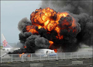
A Boeing 737-800 operated by China Airlines departed from Taiwan, Taoyuan International Airport on a regularly scheduled flight to Naha Airport, Okinawa, Japan. Following landing and leading-edge slat retraction, a failed portion of the slat track assembly was pressed through the slat track housing and penetrated the right main fuel tank, causing a fuel leak. Fuel that had been leaking from the right-wing tank during taxi and parking was ignited by hot engine surfaces and/or hot brakes, resulting in the aircraft being engulfed in flames.
Probable Cause: The mechanic failed to install a washer on the slat downstop assembly. Without this washer, the downstop assembly was able to fall out of the slat track. The downstop assembly then fell into the slat can, where it was later pushed through the slat can wall, initiating the fuel leak.
Japan Transport Safety Board Report: AA2009-7
Bell Helicopter, Textron, Inc, Avalon, Texas, August 7, 2012
A Bell 214ST helicopter, N409SB, experienced loss of tail rotor authority near Avalon, Texas. The pilots were not injured during the precautionary landing but the helicopter was substantially damaged.
Probable Cause: Maintenance personnel's failure to properly torque the retaining nut and install the cotter pin that secured the helicopter's tail rotor counterweight bellcrank. Contributing to the accident was the lack of detailed maintenance records that documented previous maintenance actions.
NTSB Report: CEN12LA525
Aerospatiale West, Windsor, New Jersey, September 15, 2012
Source: NTSB
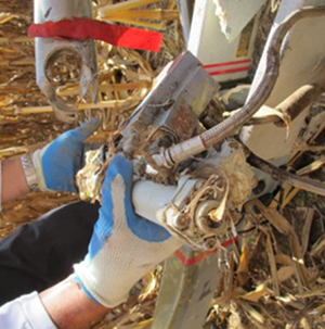
On September 15, 2012, an Aerospatiale AS 355F1, N58020, operated by Analar Corporation, was substantially damaged when it impacted terrain following an in-flight breakup near West Windsor, New Jersey. The commercial pilot was fatally injured. The flight originated from Princeton Airport (39N), Princeton, New Jersey. During flight, ground witnesses reported hearing a grinding or popping noise followed by the separation of the yellow main rotor blade.
Probable Cause: Disconnection of the upper rod end from the fore/aft servo due to severely worn threads which resulted in a loss of control and separation of a main rotor blade during cruise flight. Contributing to the accident were incorrect maintenance procedures and inadequate maintenance inspections performed by the operator and insufficient inspection criteria provided by the helicopter manufacturer.
NTSB Report: ERA12FA563
Robinson, Miami, Florida, April 3, 2013
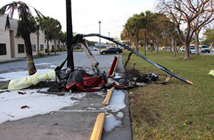
Source: NTSB
On April 3, 2013, Robinson R44, N3101H, had components separate in flight and the helicopter impacted the ground shortly after takeoff from Kendall Tamiami Executive airport, in Miami, Florida. The helicopter was registered to and operated by Bravo Helicopters, LLC. The commercial pilot and pilot-rated mechanic incurred fatal injuries. This was a maintenance test flight.
Probable Cause: The mechanic's failure to properly secure the pitch link hardware of one main rotor blade to the rotating swash plate. This resulted in the pitch link separating in flight and the pilot's subsequent loss of control. Contributing to the accident was the pilot's/owner's pressure on the mechanic to return the helicopter to revenue service.
NTSB Report: ERA13FA186
Cessna T310Q, Wichita, Kansas, September 25, 2015
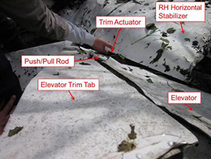
Source: NTSB
On September 25, 2015, a Cessna T310Q airplane, experienced a flight control malfunction during takeoff initial climb and impacted the ground near Wichita, Kansas. The commercial pilot was fatally injured and the airplane was destroyed. The airplane was registered to Celestial Knights, LLC, and operated by the pilot under the provisions of 14 Code of Federal Regulations Part 91.
Probable Cause: Separation of the attachment hardware connecting the elevator trim tab pushrod to the elevator trim actuator, which resulted in the elevator trim tab jamming in a position outside the limits of normal travel and a subsequent loss of airplane control.
NTSB Report: CEN15FA425
Technical Related Lessons
When completing and inspecting maintenance activities, operators should adhere to manufacturer and FAA rules and guidance regarding the use, reuse, and replacement of anti-rotation devices (i.e., locking features on threaded fasteners) to ensure aircraft operating safety. (Threat Category: System / Component Failure or Malfunction (non-powerplant) (SCF-NP))
- Due to FAA requirements, fasteners, whose loss could jeopardize safe operation of the aircraft, must incorporate two separate locking devices. The AS350 uses this dual-locking capability on its flight control fore/aft servo fasteners to provide protection against single-part failures. The dual locks include a combination of self-locking nuts and split pin couplers.
- Based on accident report findings, it is evident that Sundance reused fasteners far beyond manufacturer and FAA guidance. Following the accident, Sundance inspected all 18 of their AS350 helicopters. All the fore/aft servos were found properly connected with castellated nuts and split pins. However, maintenance findings and procurement reports show that the nuts and fasteners had not been replaced in any of Sundance’s helicopters since November 2008, three years before the accident.
Common Theme Related Lessons
It is imperative that dual lock fasteners are properly installed and that each component is in an airworthy condition. On many helicopter designs, including the AS350, a single malfunction/failure of the flight control system connecting hardware can lead to a catastrophic accident. (Common Theme: Organizational Lapse / Human Error)
- The objective of §27.607 Fasteners, and the corresponding AC 20-71, is to ensure a fastener that is subject to rotation "must incorporate two separate locking devices." Investigators looking at the Sundance fleet determined about half of the self-locking nuts from the 13 helicopters examined had no locking capability (i.e., self-locking feature was inadequate). Additionally, about half of the bolts had wear markings on the shanks.
- Investigators also determined, through laboratory testing on the accident aircraft, that the split pin was either not installed or was installed improperly.
- The NTSB also determined that the quality control inspector, the check pilot, and the accident pilot failed to notice or recognize the degraded nut or split pin installation.