
Convair 340
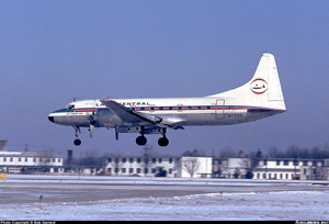
Photo copyright Bob Garrard - used with permission
Lake Central Airlines Flight 527, N73130
Marseilles, Ohio
March 5, 1967
On March 5, 1967, a Convair 340, operated as Lake Central Airlines, Inc. Flight 527, crashed near Marseilles, Ohio. All 38 persons aboard were killed, and the airplane was destroyed. The accident investigation discovered that all four blades of the right propeller separated in flight. One of the four blades penetrated the airplane fuselage in such a way that the structural integrity was significantly compromised. The massive structural damage and the loads caused by a violent yaw to the right resulted in the fuselage failing along the line of penetration and breaking apart in flight.
Further investigation of the right propeller showed that the helical splines of the steel torque piston for the blade pitch change unit were worn away and the torque cylinder was completely failed due to fatigue. A secondary failure of the steel torque cylinder occurred and prevented propeller oil pressure from being maintained and holding the propeller pitch. As a result, the blade pitch moved from coarse to fine pitch so rapidly that the propeller pitch lock mechanism became ineffective and failed to arrest the propeller overspeed. Operation at low pitch, or high revolutions, during cruise flight then caused a centrifugal force so great that the blades exceeded their design limits and separated from the propeller hub. It was later deduced that the cause of the torque piston spline wear occurred as a result of omitting a critical material hardening process during manufacturing called nitriding.
The failure of the right engine propeller to maintain proper blade pitch was the probable cause of the accident as concluded by the safety board. The root cause was due to a critical surface hardening process (nitriding) being omitted during manufacturing which caused a key propeller safety feature to fail during flight. The safety board discovered that the omission of the nitriding was associated with a special manufacturing process that disrupted the normal production flow.
History of Flight
On March 5, 1967, Lake Central Airlines Flight 527 was a scheduled passenger flight between Chicago, Illinois and Detroit, Michigan with intermediate stops at Lafayette, Indiana, Cincinnati, Columbus, and Toledo, Ohio. The airplane
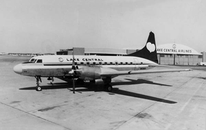
Photo copyright The Ed Coates Collection - used with permission
was a Convair 340-31, registration number N73130, equipped with Allison turbo propeller engines.
At approximately 2005 Eastern Standard Time (EST), and during the Columbus to Toledo leg, Flight 527 was on an instrument flight plan and cleared to descend from 10,000 to 6,000 feet. Cleveland ARTCC (Air Route Traffic Control Center) requested that the flight crew report leaving 8,000 and 7,000 feet. While still at 10,000 feet, the crew acknowledged the instruction. This was the last radio transmission from the flight. At 2007 EST, the airplane disappeared from Cleveland center's radar screen.
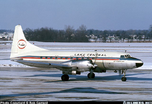
Photo copyright Bob Garrard - used with permission
Witnesses near Marseilles, Ohio stated that between 2005 and 2010 they heard sounds from an aircraft and described the sounds "like an engine revving up", "like a car stuck on ice", and "like a sports car on a drag strip". Additionally, there was an explosion followed by a heavy impact. It was subsequently determined that the airplane had impacted the ground. By 2100 it was confirmed that all 38 persons on board the flight had been killed.
Crash Site

View Larger
The crash site was two miles southwest of Marseilles, Ohio. The aircraft was in an upright, near-level attitude on a magnetic heading of approximately 360 degrees. Evidence showed that when the aircraft struck the ground, a portion of the forward fuselage was completely separated except for the control cables and the main electrical wiring bundle. At impact, the forward fuselage section had broken free and slid about 90 feet ahead of the main body of the aircraft. A 12-foot portion of the fuselage structure, interior equipment, furnishings, and the right propeller were missing. Most of the separated fuselage structure was recovered and investigators were able to reassemble the pieces and determine that the separation occurred in line with the propeller plane. From the reconstruction they were able to determine the entry pattern from the propeller as it penetrated the fuselage. There were multiple electrical wires and power feed cables cut near the penetration that appeared to have been severed by the propeller blade. Airplane control cables in the same area had failed due to overstress. The following propeller parts detached from the right engine were found at the following locations:
Propeller part discovery locations
| Propeller Components | Discovery (recovery) location at wreckage site |
|---|---|
| four propeller blades | separate locations ranging from 2,000 to 2,300 feet southeast of the main wreckage |
| number 3 torque piston | 300 feet west of the main wreckage |
| propeller hub containing the number 1, 2, 4 torque unit assemblies | 2,800 feet north of the main wreckage |
| master gear assembly | 2,000 feet north of the wreckage site |
View Larger
Further examination of the blades from the right propeller showed that all had failed in the blade root section, at the same location and in the same manner. Visual and metallurgical examinations determined that the blade failures were due to tensile overload.
It was determined that the No. 2 blade of the right engine pierced the fuselage, tip first, while moving on a tangent to the propeller arc and rotating clockwise end over end. The end-over-end rotation of the propeller blade caused it to assume a position to cut through the upper right side of the fuselage. It also continued through the interior on an upward trajectory and penetrated the upper left side of the fuselage. Investigators performed an analysis and estimated that the damage caused by the propeller blade had reduced the structural integrity of the fuselage by fifty percent. Investigators also concluded that fuselage break-up was caused by the decrease of structural strength in combination with yaw forces generated during propeller separation.
The Accident Airplane - Convair 340
The accident airplane was manufactured by the Consolidated Vultee Aircraft Corporation on November 3, 1952, as a Convair-Liner Model 340-31. The original engines installed on the airplane were Pratt and Whitney 1790kW (2400hp) R-2800-CB16 Double Wasps. However, this airplane had been converted to an Allison Prop-Jet (turbo propeller) on September 13, 1966, by Pacific Airmotive, Inc. in accordance with FAA Supplemental Type Certificate Number SA-4-1100. The conversion included installation of Allison 501-Dl3D engines and Aeroproducts A6441FN-606A propellers. The engine type design was held by the Allison Division of General Motors. Similarly, Aeroproducts was responsible for the propeller type design. At the time, Aeroproducts was a subsidiary of the Allison Division of General Motors.
It is common to refer to a Convair 340 that has been turbine-converted via the STC as a Convair 580. The Convair 580 is structurally similar to the 340 except that the vertical fin and horizontal stabilizer are larger. As delivered from the factory, a Convair 580 was equipped with the turbo-propeller STC, and also included larger horizontal and vertical stabilizers.
On September 15, 1966, Lake Central Airlines, Inc. became the owner and operator of the aircraft. The basic airframe of the aircraft had accumulated 16,216 flight hours at the time of the accident. The operational history of the propellers is listed below:
Operational history of propellers
| Installed Position | Manufacture Date | Serial Number | Total In Service Hours |
|---|---|---|---|
| Left engine | August 12, 1966 | P-987 | 372 |
| Right engine | July 29, 1966 | P-984 | 1055 |
Aeroproducts Turbo Propeller A6441FN-606A
View Larger
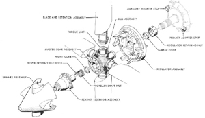
The Aeroproducts A6441FN-606A turbo propeller is a clockwise-rotating, hydraulically-controlled, constant-speed propeller. It incorporates an integral hydraulic governing system operating independently from any of the other engine systems. Electrical power is supplied to the propeller for synchronizing, phase synchronizing, and anti-icing control. The propeller diameter is 13 feet, 6 inches and the propeller weighs approximately 1,030 pounds, when installed.
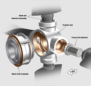
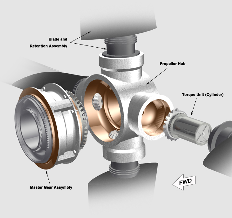
The main purpose of the propeller is to convert engine torque to thrust and regulate the torque to keep the engine at optimum design speed. The optimum engine speed is directly related to propeller blade angle, which is controlled by the integral propeller hydraulic system. In general, an increase in blade pitch results in a load being placed on the propeller shaft which then decreases the engine speed. There are five major assemblies that define the propeller installation: regulator, hub, blade and retention, feather reservoir, and spinner. All of these major assemblies provide selective pitch control, negative torque control, synchronizing, phase synchronizing, feathering and reversing features, and electric icing control.
The integral hydraulic system of the propeller assembly supplies the pressure required to change the blade angle to compensate for variation in blade loading and maintains a constant 1020 revolutions per minute (RPM). The hydraulic system is controlled by a mechanical linkage from the flight deck.
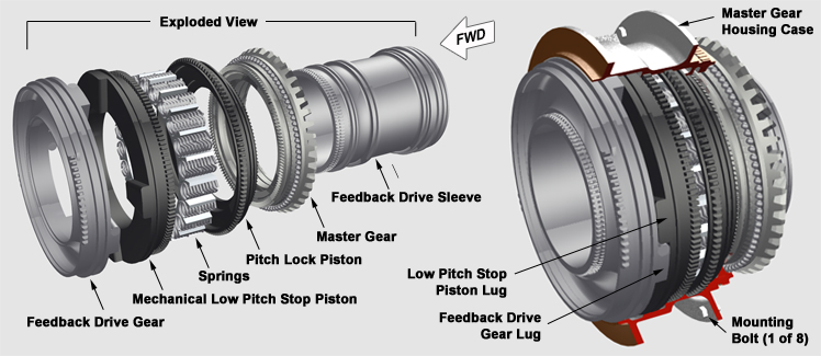
The hub assembly acts as the main structural member of the propeller. It consists of the hub, master gear assembly, and the four torque units. There is one torque unit for each blade that uses hydraulic oil pressure to control blade pitch. Hydraulic oil is delivered under pressure from the regulator to the torque units. Blade movement is accomplished by two oil passages, one to the outboard side and one to the inboard side of the torque piston. Differential hydraulic pressure on the piston determines the piston position and, thus the blade angle.
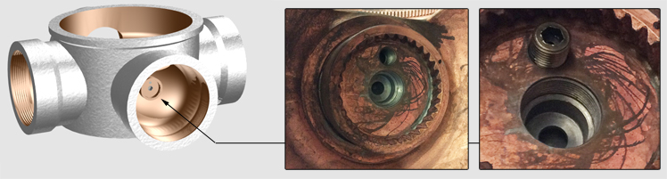
There are three basic parts that make up the torque unit: the fixed spline, the torque piston, and the torque piston cylinder.
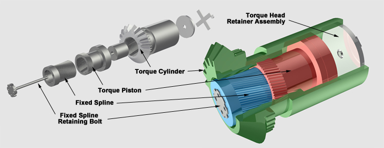
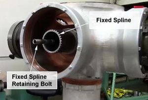
Photo copyright Pacific Propeller – used with permission
The fixed spline is fastened to the propeller hub by means of the fixed spline bolt and has external helical splines which mate with internal splines on the torque piston skirt.
The retaining bolt incorporates a tube to provide a passage for pressurized fluid to the outboard side of the piston. A port in the base of the fixed spline provides an oil passage to the inboard side of the piston. The torque piston skirt has external helical splines which mate with splines on the inside of the torque cylinder.
Linear movement of the torque piston rotates the torque cylinder and the attached propeller blade to the desired blade angles. An increase in hydraulic oil pressure on the inboard side moves the piston outward to increase blade angle. A decrease in oil pressure allows aerodynamic loading of the propeller to drive the blade toward a decreased blade pitch. The following animation shows the basic movement of torque piston as it relates to blade angle.
The master gear assembly consists of a housing, master gear, mechanical low pitch stop, mechanical pitch lock, air shutoff, and feedback mechanism parts. The master gear coordinates the movement of the individual torque units to maintain precisely the same pitch on all propeller blades. Each torque cylinder has a machined section of matching gears. This feature provides redundancy for the system, in that if one torque unit were to fail, the function of the failed unit would be transferred to the others.
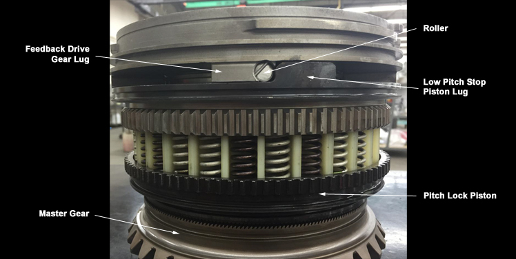
Photo copyright Pacific Propeller – used with permission
The A6441FN-606A Propeller Pitch Lock and Stop
The pitch lock and stop assembly in the A6441FN-606A propeller is a safety device attached to the front of the propeller hub and located inside a housing. It is relevant to the accident since investigators believed it failed to arrest the sudden blade movement towards low pitch at the instant the hydraulic oil pressure was lost. The pitch lock is a ring with ratchet type teeth (serrations) that are spring loaded to engage the mating teeth on the master gear in the event of an overspeed. During normal flight operations, the pitch lock is hydraulically held apart from the master gear and the pitch lock teeth are not in contact with the master gear teeth. This allows for the governor to make continuous and necessary pitch adjustments to maintain the required engine RPM. The hydraulic oil pressure forces the pitch lock piston to compress against 60 springs that are installed on the backside of the piston.
During an overspeed event, a piston inside of the pitch lock and stop hydraulic valve moves in the outward direction due to the centrifugal force from the engine RPM increase. This piston movement then relieves the hydraulic pressure holding the pitch lock. As soon as the hydraulic pressure is less than the spring force, the pitch lock piston teeth translate and engage the master gear teeth. The gears lock at the last commanded blade angle, preventing the blade angle from decreasing and arresting the engine overspeed. In summary, the pitch lock mechanism engages any time that the engine RPM has reached or exceeded 14,285.
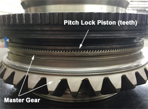
Photo Pacific Propeller - used with permission
The Flight 527 accident was a result of a propeller overspeed event caused by an instantaneous loss of hydraulic oil pressure. The sudden loss of oil pressure in the torque cylinder caused the blade centrifugal force to move to high speed which then caused the pitch lock valve to relieve the oil pressure and allow the spring force to engage the pitch lock to the master gear. However, the blade twisting occurred so rapidly and with such great force that the pitch lock mechanism was unable to arrest the rapid blade change and resulted in shearing off the eight bolts that attach the pitch lock housing to the propeller hub.
As a backup to the pitch lock, the mechanical low pitch stop is designed to prevent the blade angle from decreasing below 18.25 degrees during flight. It, too, is hydraulically controlled, but unlike the pitch lock, it is engaged during flight. That is, the same springs which push against the pitch lock piston act in the opposite direction against the mechanical low pitch to engage four lugs and mechanically stop the master gear or blade from decreasing below 18.25 degrees. During taxi operations, hydraulic oil pressure is sent to the mechanical stop to compress the springs and disengage the lock-out feature.
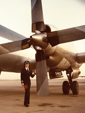
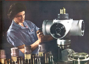
Photo copyright Capt. Gloria LaRoche – used with permission
Propeller Failure Sequence
Five events occurred in sequence, resulting in the separation of the blades from the right engine propeller hub. Investigators attributed the crash of Flight 527 to overspeed of the right propeller, leading to a structural failure within the propeller blades and their subsequent separation from the propeller hub. Following metallurgical examination, investigators concluded that all four blades failed in the blade root section and in the same manner - tensile overload.
Examination of the wreckage showed that the internal and external helical splines of the torque piston from the No. 3 torque unit were severely worn. This worn condition was attributed to the omission of nitriding of the splines during the manufacturing process. Nitriding is a surface hardening process for steel. In its worn state, the piston was free to move based on the difference between hydraulic oil pressure acting on the bottom of the piston and centrifugal force acting on the blades. The manufacturer later calculated that a piston with worn splines moves outward due to centrifugal force and is retained by the top of the cylinder cap. During propeller operation, this would increase the cylinder wall load from approximately 2,400 pounds to 44,000 pounds, with a resultant increase in stress to 99,000 pounds per square inch, exceeding the design strength of the part.
As a result of the free moving piston causing an increase in stress, the torque piston cylinder eventually failed due to fatigue. Piston cylinder failure originated on the inside of the cylinder wall and progressed around the entire circumference of the wall, resulting in the sudden rupture of the cylinder. The cylinder rupture caused an instantaneous loss of hydraulic oil pressure.
The operating conditions last reflected by the flight recorder would have resulted in a blade angle of 49 degrees. However, the sudden loss in oil pressure allowed for the aerodynamic twisting forces to move the blades from 49 degrees toward a low pitch of 21.5 degrees at an estimated rate of 130 degrees per second. As a result of this rapid pitch change, the pitch lock failed to engage and arrest the rapid pitch change. The pitch lock failure was verified by examination of the pitch lock piston gear teeth and the master gear mating teeth. The mating teeth of both parts were badly damaged in a similar manner over an arc of about 120 degrees.
Finally, the master gear assembly separated from the propeller hub. X-rays of the pitch lock revealed that the pitch lock piston block-out lug was against the master gear lock block-out cam, a position which corresponded to a propeller blade angle of 21.5 degrees. The lugs are provided on the pitch lock piston to prevent further engagement less than 21.5 degrees. Pitch lock engagement failed due to the loads imposed during engagement. The eight mounting bolts then failed in shear due to the high loads.
Following separation of the master gear assembly from the propeller hub, including the loss of all propeller hydraulic oil, the blades became free to move toward a flatter pitch, lower than that normally permitted by the low pitch stop. As blade pitch decreased, propeller speed increased until all four blades failed in tensile overload. Investigators established that after separation, blade No. 2 struck the airplane, initiating the fuselage structural failure.
An animation of the propeller failure sequence is available below:
Nitriding
Nitriding is a surface-hardening treatment that was first developed in the early 1900s. It is a specialized heat treatment that produces a thin surface layer with high hardness on a wide variety of steels. Nitrided surfaces have excellent wear resistance and provide anti-galling properties. Fatigue life and corrosion resistance are improved. An additional advantage of nitriding is that it results in a surface hardness that is resistant to softening at temperatures up to the process temperature (approx.975°F). Another benefit of nitriding is that the case hardness is developed at lower temperatures and cooled slowly (i.e. no quenching), which means that distortion is reduced to a minimum.
Source: S. Lampman, Introduction to Surface Hardening of Steels, Heat Treating, Vol 4, ASM Handbook, ASM International, 1993, p 263.
View Larger
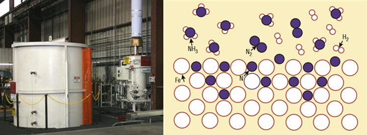
The Aeroproducts procedure for hardening the propeller torque pistons and cylinders was to place the parts in a nitriding furnace for 48 hours at a temperature of 975°F. During nitriding the heated steel is exposed to ammonia gas in the furnace. At the high temperature environment of the furnace, the ammonia partially decomposes into nitrogen, N2, and hydrogen, H2, gas according to the following reaction: 2NH3 <=> N2 +3H2.
Since the ammonia gas is in direct contact with the steel surface, the nitrogen gas that is developed according to the above equation is then catalytically cleaved into nascent nitrogen atoms, N (see illustration of the nitriding process). The following non-equilibrium chemical reaction describes this process:
2NH3 -> 2N + 3H2.
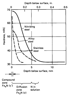
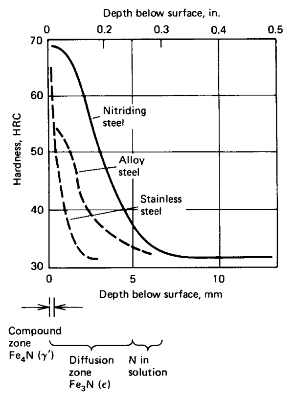
The effectiveness of the process depends on formation of nitrides in the steel, which is heavily influenced by the duration the steel is exposed to the gas. This process is a ferritic (iron) thermochemical method of diffusing nitrogen into the steel surface. This diffusion takes place at relatively low temperatures (approx.1000° F) and the hardening occurs as the part cools. Depth of the surface hardness is related to the duration that the steel is exposed to the gas. The longer the steel is exposed to the gas, the more time the gas has to diffuse, react with alloying elements, and form nitrides. At the surface, a compound zone and an underlying diffusion zone forms. The compound zone, also known as the white layer, consists predominantly of e-Fe2-3(C, N) and/or g'-Fe4N phases and is removed after nitriding because it is brittle. The diffusion zone, however, is hardened and composed of interstitial solid solution of nitrogen dissolved in the ferrite lattice (g'-Fe4N and/or a'-Fe16N4 phases) and nitride and/or carbonitride precipitation for the alloy steels containing the nitrides forming elements. The diffusion zone is responsible for a considerable enhancement of the fatigue endurance.
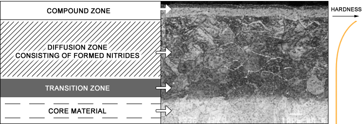
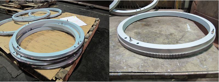
Photo copyright MetLab Co. – used with permission
Manufacturing Process Interruption
Investigators established that during manufacturing, ten torque pistons were removed from the production flow in order to conduct a statistical study. The study was intended to determine the part growth associated with nitriding. The subject torque pistons were removed from the normal production flow and taken to a laboratory. Identifying marks were applied and study-related dimensions were determined. Following the initial portion of the study, it was intended that the subject torque pistons would be reintroduced into the production process because they would have undergone nitriding as part of the statistical study.
For reasons the investigators could not readily determine, the subject torque pistons were returned to the production process in a sequence that resulted in nitriding being omitted. After cleaning, a nitrided part is not easily distinguished from a part without nitriding, so assemblers would be unable to visually identify a non-nitrided part. Final inspections prior to assembly included a Rockwell hardness check and a magnafllux test on 100% of production parts. Either of these inspections should have identified the non-nitrided parts and resulted in their rejection. The omission of the nitriding, which is a hardening process for steel, resulted in ten torque pistons that were under strength, some of which subsequently failed during normal operation.
The National Transportation Safety Board (NTSB) issued 13 findings, the majority of which concerned the mechanical and process failures that led to the failure of the propeller and the subsequent accident. The findings are included here in their entirety from the accident report:
"1. The crew of Flight 527 were properly certificated and qualified for the flight.
2. The aircraft was properly certificated and maintained but at the initiation of Flight 527 it was not airworthy due to a defective torque piston in the right propeller.
3. Flight preparation was routine, and the flight progressed with no apparent difficulty until it was near Marseilles, Ohio, at 2006.
4. Loads on the torque cylinder caused by the failed torque piston of the No. 3 blade: of the right propeller exceeded the finite fatigue life of the cylinder and it failed in fatigue.
5. The loss of oil pressure in the right propeller due to the failed torque cylinder caused the propeller pitch to decrease at a rate which exceeded the propeller pitch lock capability.
6. The right propeller oversped, causing the blades to separate in overstress.
7. The No. 2 propeller blade of the right propeller penetrated the fuselage, destroying the structural integrity to the extent that together with the force of a right yaw attending the propeller separation, the fuselage failed along the line of the propeller penetrations.
8. The torque piston of the No. 3 blade had not been nitrided for surface hardening of the helical splines during manufacture.
9. The omission of the nitriding process was not detected by inspection.
10. The omission of the nitriding process was associated with the movement of ten torque pistons from the normal production flow to the Allison laboratory and return to the production process.
11. The Allison quality control system lacked the accountability necessary to assure the requisite quality of the individual parts.
12. The metal contamination oil check to isolate defective torque pistons did not serve the intended purpose.
13. Allison underestimated the seriousness of the defective torque piston problem."
The NTSB further determined the probable cause of the accident to be (from the accident report):
"The probable cause of this accident as determined by the safety board was the failure of the right propeller due to omission of the torque piston nitriding process during manufacture. In addition, the failure of manufacturing quality control to detect the omission was a causal factor."
The entire NTSB accident report is available at the following link: (NTSB Accident Report)
Further investigation at the manufacturing facility revealed that the procedure for confirming parts were nitrided was to sample for case hardness by checking the splines of the toque pistons with a file of Rockwell hardness 89 (RC 89). An improperly hardened surface would become marked from the file check and the inspector would be able to feel drag on the file. The Allison inspector responsible for this verification stated that in the seven years performing the file check he had never discovered a torque piston that did not pass the hardness test. It is important to emphasize an inconsistency in the NTSB accident report which reads that the nitrided parts were sampled but the technician explained that it was his habit to inspect all nitrided parts for hardness using the file method. The word sampling implies that some parts were inspected.
As soon as the ten torque pistons were verified to be missing the nitriding process, Allison discovered the parts incurred an out-of-position production flow disruption. The parts were repositioned from production flow to the laboratory for the purpose of a statistical study to determine part growth during nitriding. While in the laboratory, the parts received special markings at distinct locations on the spline end. All the defective torque pistons were verified to have the special markings. Allison could not determine exactly how the omission in nitriding occurred, especially given that there were verifiable markings that indicated all ten parts were nitrided.
The National Transportation Safety Board did not issue any formal recommendations as a result of this accident.
Civil Air Regulations (CAR) 14.100 Scope
CAR 14.101 Materials
CAR 14.102 Durability
These three regulations are linked here: (CAR 14.100 thru .102)
CAR 14.151 Centrifugal Load Test
Factory processes at Allison included tests to verify that parts had been properly nitrided. Samples were tested for case hardness by checking the splines of the toque pistons with a file of Rockwell hardness 89 (RC 89). An improperly hardened surface would retain file marks and the inspector would be able to feel drag on the file. Investigators interviewed Allision's inspectors, and one inspector stated that in seven years performing the file check he had never discovered a torque piston that did not pass the hardness test. The inspector further stated that it was his habit to inspect all nitrided parts for hardness using the file method.
Just prior to the accident, Allison had identified several manufacturing lots of torque pistons that had potentially not been nitrided during the manufacturing process. Following the accident, the number of potentially defective parts was reduced to ten. Allison discovered the ten identified parts had been subject to an out-of-position production flow disruption. The parts were repositioned from production flow to a laboratory for use in a statistical study to determine part growth during nitriding. While in the laboratory, the parts received special markings at distinct locations on the spline end. All the defective torque pistons were verified to have the special markings. Allison could not determine exactly how the omission in nitriding occurred, especially given that there were verifiable markings indicating that all ten parts had been nitrided.
Investigators determined that Allison had an FAA-approved quality system that utilized full-time personnel furnished with suitable working conditions, tools, and equipment to perform their duties. However, investigators could not determine how the ten defective torque pistons had missed the nitriding process, especially when they all had distinguishing marks on the spline end placed there during the statistical study. Investigators were further unable to identify how breakdowns in Allison's quality control system could occur in such a way that the omission of nitriding would not be detected.
Quality Control
- The torque piston of the No. 3 blade had not been nitrided for surface hardening of the helical splines during manufacture. This caused a premature fatigue failure of the splines which contributed to the failure of the torque cylinder and then, loss of oil pressure.
- There was a failure of Allison's manufacturing quality control process to detect the omission of nitriding and ensure requisite quality in accordance with type design.
- Allison's quality system failed to properly account for the ten torque pistons that underwent a statistical growth analysis. This disruption to the normal flow of production was associated with missing nitride treatment.
Propeller Design
- The propeller pitch lock system and hydraulic oil supply line were unable to arrest a blade pitch decrease caused by a sudden loss in oil pressure.
- The eight fasteners attaching the pitch lock housing to the hub were unable to properly secure the mating parts in the event of an instantaneous blade pitch arrest.
- The final inspection steps during the manufacturing process were sufficiently robust to identify missing key processes such as heat treatment.
- The pitch lock assembly was capable of arresting a low pitch condition, thereby preventing propeller overspeed.
Approximately a week before the accident, a propeller from an Allegheny Airlines Convair, with 454 service hours since new, was received for repair at the Allison facility with the complaint that it failed to reverse. Upon disassembly three days later, the propeller was disassembled, revealing two torque pistons with badly worn helical splines. Metallurgical examination determined that the splines on both pistons had not been nitrided for surface hardening during manufacture.
Allison immediately began an investigation of heat treat and final inspection records to isolate any other torque pistons which could have missed the nitriding (heat treat) process. A group of 234 suspect torque pistons was identified by comparing serial numbers and nitriding and final inspection dates. It was determined that the suspect parts were processed in several lots between February and June 1966. By examining the assembly records, it was further possible to identify the propellers in which the suspect parts were installed and, from the propeller serial numbers, to identify the operators of the parts.
On March 3, all of the affected operators were instructed to perform a special oil analysis intended to reveal metal particles from non-nitrided (soft) torque pistons. The analysis consisted of a visual check of the magnetic drain plug, oil color verification, and filtration of the oil to gather any loose metal particles. The following day, Lake Central maintenance verified their fleet of four Prop-Jet Convairs and determined that all had successfully completed the oil analysis, including the accident airplane.
Following the accident, Allison implemented several changes to the propeller design, manufacturing procedures, and quality assurance processes.
Design Improvements
- Incorporation of a control orifice in the increase pitch oil supply line of each torque piston assembly. This orifice is a precision-drilled opening in the hydraulic flow path. The orifice was intended to restrict the rate of oil loss to a rate that would prevent a reduction in blade pitch of more than nine degrees per second. Prior to this design enhancement, testing showed that a sudden loss of oil pressure, similar to that experienced during the accident, would have caused a blade pitch reduction of 130 degrees per second. During propeller certification, the maximum change in pitch was tested at 40 degrees per second. Allison had considered this the maximum rate which could result from any single failure.
- The pitch lock housing-to-hub retaining fasteners ultimate tensile strength was increased from 175,000 to 220,000 pounds per square inch and the number of fasteners was doubled from 8 to 16.
- The torque cylinder fatigue life was improved by redesigning it for infinite life under all types of failure scenarios.
Manufacturing Processes
- During manufacturing, the torque cylinder was serialized prior to the nitriding process, which provided a better basis for strict accountability of each part.
- During manufacturing, specific colored medallions were placed in each container of parts which showed the status in the production flow and helped identify critical manufacturing processes such as nitriding and stress relief.
- During manufacturing, a procedure was implemented to use a Rockwell hardness tester to verify the hardness of the spline end of the piston. This tester was used in conjunction with the original file method, since the tester can check the hardness only on the spline end. Previously, the technician performed the hardness check only by running a file over the nitrided surface. The use of a logbook was also adopted in order to allow the recording of the hardness and serial number of each torque piston.
67-12-01
Removed fixed splines that did not pass the required core hardness check.
67-17-01
Required removal and inspection of the fixed spline.
This AD superseded AD 67-12-01.
67-20-01
To prevent serious overspeeds and to make the propeller pitch lock more effective under remote combinations of critical component failures, this AD required the installation of a flow restrictor in the pitch increase hydraulic supply line and replaced the eight hub attaching fasteners with high strength bolts.
Airplane Life Cycle:
- Design / Manufacturing
Accident Threat Categories:
- Structural Failure
Groupings:
- N/A
Accident Common Themes:
- Organizational Lapses
- Flawed Assumptions
- Unintended Effects
Organizational Lapses
Accident investigators learned that during the manufacturing process, ten torque pistons had not undergone the required nitriding process. It was established that these torque pistons had been removed to a laboratory at Allison as part of a study on part growth during nitriding. When the subject torque pistons were returned to the manufacturing process, they were returned to a stage that allowed them to skip the nitriding process, rather than undergo the process as intended. The ten untreated torque pistons were identified as having undergone the nitriding process. All ten were installed in propeller assemblies, with one being the cause of the propeller failure on the accident airplane. Investigators cited lapses in Allison's manufacturing inspection and quality control processes for allowing incorrectly manufactured parts to be installed on propellers and delivered to customers.
Flawed Assumptions
- The pitch lock and stop feature incorporated in the design of the master gear assembly was intended to prevent a blade movement towards low pitch in the event of a loss of oil pressure. In this accident the mechanism was defeated when the torque cylinder failed. During certification testing, the pitch lock was tested to arrest a blade angle movement of 40 degrees per second. Post-accident testing determined that blade movement as a result of a sudden loss of oil pressure could result in a blade movement of 130 degrees per second.
- Similarly, the master gear mounting flange was designed to hold the reaction forces of the pitch lock and stop mechanism. On the accident airplane, when oil pressure was suddenly lost, the reaction forces from the pitch lock and stop caused complete separation of the master gear assembly from the propeller hub. All eight fasteners had failed to secure the master gear assembly.
- One week before the Lake Central Flight 527 crash, Alison received a propeller from an operator that had failed to reverse during normal operation. Allison determined that the torque piston spline had not been nitrided. Four days later, Allison notified affected operators and instructed them to perform a mandatory special oil check. It was reasoned that the magnetic drain plug would show evidence of metal particles and positively identify a failed torque piston. Lake Central maintenance personnel performed the oil check the day before the crash, and no evidence of metal particles was detected. Investigators subsequently concluded that the special oil check had failed to serve its intended purpose.
Unintended Effects
Allison discovered that a laboratory study of nitrided parts disrupted the typical production flow. Ten parts were repositioned from production flow to the laboratory for the purpose of a statistical study to determine part growth during nitriding. While in the laboratory, the parts received special markings at distinct locations on the spline end. Upon return from the laboratory, the subject parts were returned to the manufacturing flow in a manner that caused them to skip the required nitriding process. Failure of one of the non-nitrided parts was a causal factor in this accident. Investigators were unable to determine how the non-nitrided parts were returned to the manufacturing process without having undergone nitriding.
Atlantic Southeast Flight 529, Embraer EMB120RT, N256AS
Location: Carrollton, Georgia
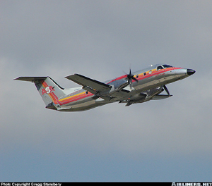
Photo copyright Greg Stansbery - used with permission
Date: August 21, 1995
Approximately 30 minutes after departing from the Atlanta Hartsfield International Airport, Atlanta, Georgia, an Embraer EMB-120RT airplane, operated as Flight 529 by Atlantic Southeast Airlines Inc., experienced the loss of a blade from the left engine propeller while climbing through 18,100 feet. The airplane crashed near West Georgia Regional Airport, Carrollton, Georgia, while attempting an emergency landing. The crash killed seven passengers and the captain.
The in-flight separation of the propeller blade resulted in failure of the left engine mount, displacing the propeller and gearbox to the left side of the wing. This resulted in excessive drag, loss of wing lift, and reduced directional control of the airplane. The NTSB determined that the propeller blade fracture was caused by a fatigue crack originating from multiple corrosion pits that, due to ineffective maintenance procedures, had not been discovered.
The accident blade had initially been removed from service after failing an on-wing ultrasonic inspection. However, accident investigators determined that the inspection procedure used to detect cracks and corrosion in the taper bore surface of the blade spar was inadequate. Additionally, inadequate training of maintenance personnel, and poor communication by the propeller manufacturer, led to misapplication of the propeller repair procedure, allowing the accident blade to be returned to service with an undetected crack.
See accident module
Atlantic Southeast Airlines Flight 2311, Embraer EMB-120
Location: Brunswick, Georgia
Photo copyright Frank C. Duarte Jr. - used with permission
Date: April 5, 1991
On April 5, 1991, Atlantic Southeast Airlines, Inc., Flight 2311, an Embraer EMB-120, N270AS, crashed during a landing approach to runway 07 at the Glynco Jetport, Brunswick, Georgia. The flight was a scheduled commuter flight from Atlanta to Brunswick, Georgia, and was being conducted under instrument flight rules. The airplane was operating in visual meteorological conditions at the time of the accident. Due to the crash, the aircraft was destroyed. The two pilots, the flight attendant, and all 20 passengers were killed.
Flight 2311 was cleared for a visual approach to Glynco Jetport a few minutes before the accident. Witnesses reported that as the airplane approached the airport, it suddenly turned or rolled to the left until the wings were perpendicular to the ground. The airplane then fell in a nose-down attitude and disappeared out of sight behind the trees.
The NTSB determined that the probable cause of this accident was: "...the loss of control in flight as a result of a malfunction of the left engine propeller control unit which allowed the propeller blade angles to go below the flight idle position. Contributing to the accident was the deficient design of the propeller control unit by Hamilton Standard and the approval of the design by the Federal Aviation Administration. The design did not correctly evaluate the failure mode that occurred during this flight, which resulted in an uncommanded and uncorrectable movement of the blades of the airplane's left propeller below the flight idle position."
See accident module
Technical Related Lessons
Propeller control system failures or malfunctions that result in propeller blade angle excursions below the low pitch stop (flat/reverse pitch angles) can result in propeller overspeed and catastrophic failure of the propeller. Propeller failures of this type have the potential to cause catastrophic airplane structural failure. (Threat Category: Structural Failure)
- The NTSB report concluded that all four blades of the No. 2 propeller experienced a tensile overload failure at the blade root section as the result of a propeller overspeed. Investigators determined that after release from the hub, the No. 2 blade pierced the fuselage. The propeller passed through the upper right side of the fuselage, continued through the interior, and exited on the upper left side of the fuselage. It was estimated that the damage reduced the structural integrity by half. The break-up of the fuselage was caused by decrease of structural strength in combination with yaw forces generated during propeller separation.
Common Theme Related Lessons
Implementation of out-of-sequence activities that interrupt normal production flow should result in application of special processes to ensure that affected parts are reintroduced into the production line to allow accomplishment of all required manufacturing processes. (Common Theme: Organizational Lapses)
- Gaps existed in Allison's quality control system that resulted in parts, following out-of-sequence checks, being re-introduced into the manufacturing process without completion of the heat treating process. Specific quality control procedures should be adopted in order to insure completion of all necessary manufacturing steps.