
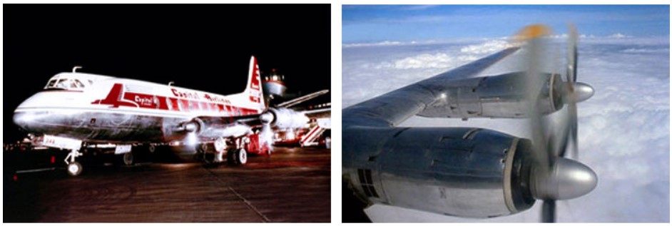
Vickers-Armstrongs Viscount 700
Capital Airlines Flight 20, N7462
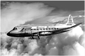
Photo copyright Richard Stanton Collection (Viscount Network) - used with permission
Charles City, Virginia
January 18, 1960
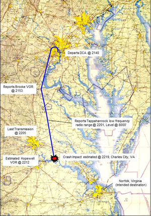
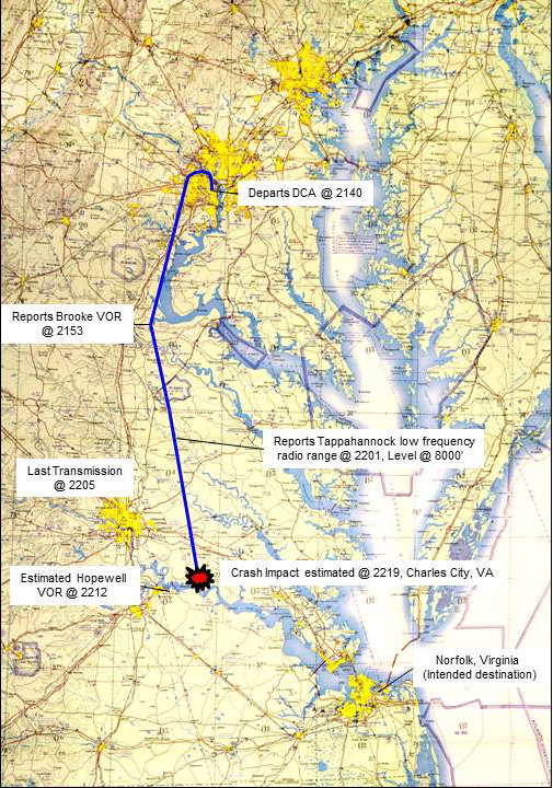
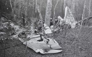
Capital Airlines Flight 20 was a regularly scheduled passenger flight from Chicago Midway Airport to Norfolk, Virginia. A stopover was made at Washington National Airport. During the stopover at National Airport, N7462 was substituted for the original airplane. Flight 20 departed National airport at 2140 with 46 passengers and a crew of 4. The flight was on an IFR (Instrument Flight Rules) plan with a cruising altitude of 8000 feet. Icing conditions were forecast for the route of flight. At approximately 2205, four minutes after passing Tappahannock low frequency range, Flight 20 acknowledged a clearance issued by Norfolk Center. This was the last communication received from the flight, at which time there was no indication of any difficulties. Approximately 14 minutes later, the aircraft crashed and burned near Charles City, Virginia, killing all persons on board.
The Civil Aeronautics Board (CAB) investigated the accident and concluded that the accident was caused by the crew's delayed arming of the engine ice protection systems while flying through icing conditions. This resulted in flame-out of all four engines, and automatic feathering of all four propellers. This condition existed for a sufficient time to cause a drop in battery energy, inhibiting the unfeathering of sufficient engines to maintain flight.
History of Flight
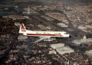
Photo copyright Peter Gates Collection (Viscount Network) - used with permission
Capital Airlines Flight 20 departed Washington National Airport on runway 36 at 2140 local time on a planned 48 minute flight to Norfolk, Virginia. The flight proceeded normally, contacting Washington Air Route Traffic Control (ARTC) when over Springfield, and was cleared to 8000 feet. Upon reaching Tappahannock at 2201, the flight was cruising at 8000 feet, and contacted Norfolk ARTC. At 2205 Norfolk ATC provided clearance for the remainder of the intended flight, which was acknowledged by Flight 20. This was the last transmission received from the flight.
Inclement weather conditions prevailed during the flight. A low pressure system was situated over eastern Michigan and the Lake Erie area with a trough extending southeastward to a developing low over southeastern Virginia, where the destination airport was located. Moderate to heavy icing was expected over portions of the planned flight route.
View Larger
Investigators believed that at some point between 2205 and 2219, all four engines lost power and their propellers automatically feathered due to ice ingestion in all four engines. Ice ingestion was believed to have been the result of delayed actuation of the engine ice protection system. Delayed actuation would have allowed substantial ice accumulations to form on the engine inlets. Following actuation, the accumulated ice would have been liberated from the engine inlets, allowing it to be ingested into each engine. Studies performed by the investigation indicated that, based on meteorological conditions at the time of the accident, this ice accumulation could have produced an ice depth of ¼ to ½ inch, and ingestion of ice in those quantities could have resulted in the failure of each affected engine. The investigation believed that all four engines failed while the airplane was still at cruise altitude, but was not able to positively establish that fact.
In the delayed actuation scenario, ice accumulation on the circumference of a Rolls-Royce Dart engine inlet would have released shortly after actuation of the system, and been ingested by the engine. The investigation believed that ice ingestion occurred on all four engines, and resulted in immediate thrust decay, engine failures, and automatic feathering of all four propellers.
Investigators concluded that more than one engine failed due to ice ingestion while the airplane was still at cruise altitude, necessitating an immediate descent to maintain airspeed. The investigation further believed that once the engines failed, the electrical system was not switched to the emergency electrical bus. The result would be that the airplane systems would continue to function using battery power, but would, in 1 ½ to 2 minutes, deplete the battery to levels that would prevent electrically actuated unfeathering of the propellers, and restarting of the engines.
Investigators believed that the crew initiated a dive in order to gain airspeed and cause the propellers to mechanically unfeather. Airspeeds of 150 knots were required to drive engines 1 and 4 out of feather, while 180 knots was required to drive engines 2 and 3 out of feather. In support of the theory that all engines failed while the airplane was still at or near its cruise altitude, the investigation believed that if two engines had continued to operate, the airplane would have been able to maintain altitude while restarting two failed engines.
At some point engine 4 was successfully restarted. During this period witnesses on the ground reported hearing noises determined to most likely be engine surging. Investigators linked these witness reports to an accumulation of fuel in the engines during repeated relight attempts, resulting in explosive relights, and engine surges. After the successful relight of engine 4, power was advanced in an attempt to arrest the descent while proceeding with relight procedures on the remaining engines. This resulted in the airplane entering a circling left turn.
Engine 3 was also successfully restarted, but the thrust asymmetry produced by the two operating engines on the right side of the airplane resulted in difficulties controlling the airplane. Flight testing following the accident demonstrated that with three engines inoperative, and engine 4 at high thrust, full right rudder and aileron were required to maintain directional control.
During the accident sequence, as the airplane descended, investigators believed that multiple attempts were made to restart the remaining engines. However, impact with the ground occurred before the remaining engines could be successfully restarted. The airplane impacted wings level, at a pitch attitude of 8 degrees nose up, and with no forward velocity. Engines 3 and 4 were developing thrust at impact, while engines 1 and 2 remained feathered.
Investigators listed several factors that may have contributed to the delay by the crew in arming the ice protection system:
- The flight crew may not have been aware of recent regulatory changes stipulating that "the ice-protection systems for all four engines must be switched 'ON' during flight at all times when the indicated outside air temperature is below plus 10ºC, except when it is certain that no icing will be encountered."
- The crew may not have armed the ice protection system until observation of visible indications of ice accretion.
- Variations between the outside air temperature gauge and the anti-icing thermostatic probe indications may have led to indications of 5ºC, when the actual temperatures may have been as low as 2ºC.
An animation of the accident sequence is below:
Ice Protection Systems and Procedures
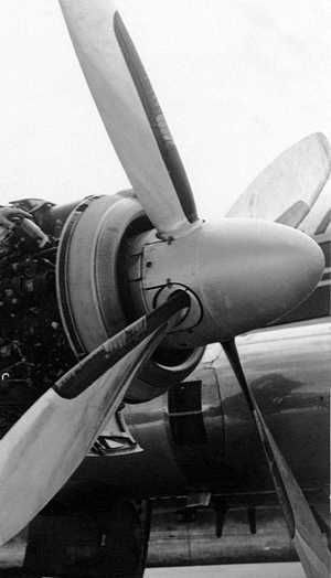
Photo copyright Jim Bruce Collection (Viscount Network) - used with permission
The Viscount was approved for flight in icing conditions and had been in service for several years at the time of the accident. The aircraft had multiple systems intended to prevent, or mitigate ice formation on the engines, propeller, and airframe. The engines and propellers utilized an anti-ice system. An anti-ice system intended to prevent ice buildup, differing from a de-ice system (pneumatic boots) that may be activated to shed accumulated ice.
Operation of the engine/propeller anti-ice system depended upon having the system manually activated by the flight crew when conditions for icing were anticipated. Flight manual procedures required the anti-ice systems to be activated when conditions conducive to icing were anticipated, specifically temperatures slightly above freezing and lower, and the presence of visible moisture. Ice would be evident to the crew via formation on the windshield wipers. However, upon visual indications of ice, investigators concluded that substantial ice may have already accreted on the engine inlets. Flight manual procedures required activation of engine/propeller anti-ice systems when entering icing conditions.
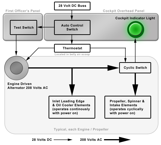
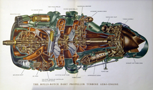
The anti-ice system for the Dart engine utilized multiple electric heating elements around the inlet to the engine compressor and the inner portion of the propeller leading edges. The anti-ice system was activated by the flight crew when conditions conducive to ice formation existed (ambient air temperature 5° C (changed to 10° C in July 1958) or below, and visible moisture).
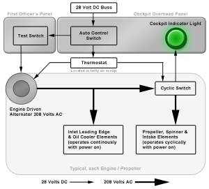
Engine anti-ice systems were activated via a switch for each engine / propeller. The switch provided DC power to a control circuit that energized a cyclic switch via a thermostat. The thermostat limited system operation to a pre-determined temperature range. With the control switch "ON" and the ambient temperature within the pre-set range of the thermostat, AC power from the respective engine generator was directed to the electric heating elements in the engine air intake. Indicator lights (cycling lights) adjacent to the switches provided a status of operation, alternating between bright and dim 12 times a minute, when measured air temperature was between 5° C and minus 6° C.
View Larger
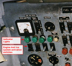
Photo copyright Clive Worboys (Viscount Network) - used with permission
View Larger
The engine anti ice circuit would not activate at ambient temperatures above plus 5° C. The temperature sensing in some earlier aircraft was found to be influenced by compressibility effects at the inlet face, causing the ambient air temperature to be as low as plus 2° C when the indicated reading was 5° C. As a consequence, in July 1958 the activation temperature for the engine anti ice system was changed from plus 5°, to 10° C, via Air Registration Board (ARB) Change 15 to the Viscount flight manual. Although the procedural change to select engine anti ice below 10° C was in effect at the time of this accident, the thermostats in the engine anti ice circuit would not allow power to the heating elements until the temperature dropped to 5° C. The Capital Airlines (subsequently United Airlines) fleet was subsequently retrofitted (by April 1961) with thermostats allowing operation of the engine anti ice system at or below 10° C.
The flight manual revision also specified the following procedure for inadvertent icing encounters, or icing encounters that might occur before the system could be switched on:
View Larger
- Switch 'ON' ice-protection systems on Engines 1 and 3.
- Observe that the cycling lights indicate correctly.
- If both engines run normally for three minutes, switch ‘ON' the ice-protection systems on Engines 2 and 4.
- If descending into air conditions where the temperature is above 0º C indicated, it is advisable to discontinue the descent until all four engines are running normally, i.e. for six minutes.
Circumstances relative to the accident flight led investigators to believe that there had been a delay in activating the engine anti-ice systems. Testing performed during certification of similar Dart engines showed that the engines would flame out from ingestion of 3.5 to 4 pounds of ice, equivalent to the release of ¼ to ½ inch thickness of ice from the inside part of the engine inlet cowling. The investigation believed, based on the recorded meteorological conditions at the time of the accident that the accumulated ice on all four engine inlets would have been in the range of ¼ to ½ inch.
An animation of how the engines were affected by the delayed actuation of the anti-ice system is below:
Upon activation of the engine and propeller anti-ice systems, accumulated ice was shed, resulting in a roll back or flame out of all engines. The investigation concluded that ice shedding, and subsequent flameouts occurred either simultaneously, or over a short time period.
Propeller Feathering System
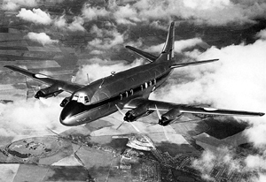
Photo copyright Charles E. Brown (Viscount Network) - used with permission
Propeller feathering systems were developed to minimize resulting drag following an engine failure. When feathered, the propeller blade angle would be aligned closely with the airflow around the engine. If the propeller were not feathered, the airflow over the propeller would cause rotation (wind milling), increasing drag. Automatic feathering systems came into widespread use on large transport airplanes in the 1940s. The auto feather system rapidly recognized an engine failure and feathered the propeller without intervention by the flight crew. The auto feather system was typically armed for takeoff and climb out. A description of an auto feather system from ANC-9 (Aircraft Propeller Handbook) is available at the following link: Excerpt from ANC-9 Propeller Handbook
Certification regulations relative to airplane performance objectives following a single engine failure led to the development of automatic feathering systems in order to reduce the drag associated with an engine failure and maximize available airplane performance. However, since takeoff performance is predicated on only a single engine thrust loss, engine isolation requirements necessitated design safeguards be incorporated to prevent the occurrence of multiple auto feather events during critical phases of flight, such as takeoff. These two requirements (i.e. drag limiting, and engine isolation) led to the development of auto feather systems that were isolated between engines and prevented the automatic feathering of multiple propellers.
View Larger
Further, operating rules required that a flight crew defer propeller feathering during the takeoff/initial climb and concentrate on flying the airplane during this critical phase. Upon reaching a safe altitude, attention could then be diverted to manually feathering the propeller on a failed engine. The auto feather system thus allowed for improved takeoff and climb performance because of the drag reduction associated with feathering the propeller immediately upon detection of a power loss. The advantage of an auto feather system was thus twofold; automatic recognition of and corrective action for the failed engine and improved take off and climb performance.
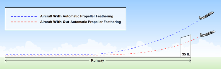

Photo copyright Mike J Sessions (Viscount Network) - used with permission
View Larger
The automatic propeller feathering systems on the Viscount were not interconnected, in that the automatic system was capable of automatically feathering more than one engine following situations that may result in multiple engine torque loss (e.g. multiple-engine bird ingestion, ice ingestion, etc.). It had been a U.S. design requirement to limit auto feathering to a single propeller, by means of an electrical relay which would transfer electrical power to only one feathering solenoid, preventing subsequent automatic feathering on additional engines. This requirement arose out of concern for multiple-engine events which would not necessarily result in multi-engine failures, but would be recoverable (e.g., minor multiple-engine bird ingestion, ice ingestion, etc.) Manual feathering on more than one engine was available via manual controls. British certification requirements at the time of Viscount certification did not require isolation of the automatic feathering functions. As the engines on Capital flight 20 ingested ice, they rolled back to an extent that the auto feathering criteria (torque below 50 foot-pounds, and rpm commanded above 13,400 rpm) were met, initiating automatic propeller feathering on multiple engines.
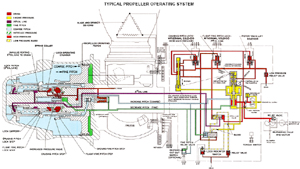
The Dowty Rotol propellers on the Viscount operated in a pitch range between 0 and 84 degrees. Pitch angles between 0 and 24 degrees were limited to ground operations. Eighty-four degrees represented the blade angle in the feathered position. Blade pitch was controlled hydraulically by engine oil boosted in pressure by the propeller control unit (PCU) pump. The boosted hydraulic pressure acted upon a piston, which was opposed by a spring force. The piston was linked to the blade pitch change mechanism. A control valve in the PCU provided oil pressure to the front of the piston for coarse pitch and to the rear for fine pitch. When propeller feathering was commanded, oil was directed to the front of the piston resulting in the blade pitch being driven to the 84-degree limit.
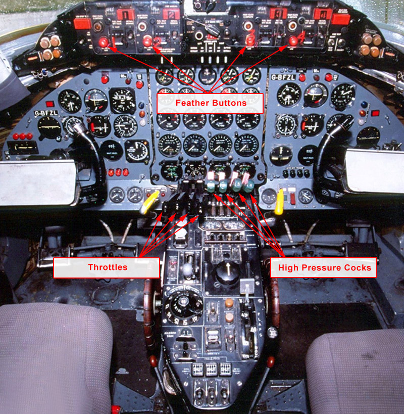
The flight crew could manually feather the propeller by moving the high-pressure cock (fuel shutoff) lever fully aft to the feathering position, or by pushing the feathering button. Either of these methods increased oil pressure against the piston, increasing blade pitch. The high-pressure cock levers were mechanical linkages to fuel shut off valves. The levers were positioned forward (fuel valve open) for engine operation. When the lever was moved aft to the intermediate position, fuel flow to the engine was shut off. Moving the lever fully aft lifts the piston valve in the PCU via a mechanical link. In this position oil pressure from the PCU drives the blade angle to the feathered position. The normal feathering procedure utilized the feathering button that would actuate an electrically operated feathering pump that boosted oil pressure, driving the propeller to the feathered position. When unfeathering, and starting the engine in flight, the feathering button is pulled, and the engine ignition system is energized for 30 seconds to ignite fuel and start the engine.
The propeller would also feather automatically if the engine failed, as sensed by a drop in output torque. The auto feather system feathered the propeller when torque dropped below 50 foot-pounds, the throttle was in a position to command an engine rpm above 13,400 rpm, and the high-pressure cock was open.
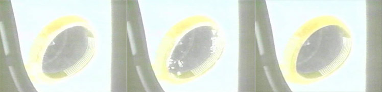
A video, created soon after the Viscount entered commercial service, and illustrating the inflight propeller feathering and unfeathering procedures is below:
Aircraft Electrical System
As a consequence of the loss of power on all engines, the existing electrical load was transferred to the two aircraft batteries. An emergency electrical bus was available to supply power to essential equipment. With emergency power selected and the batteries fully charged, power would be available for 30 minutes to an hour for essential items (primarily cockpit instrumentation, lighting, and other essential equipment).
The Viscount 28-volt electrical system consisted of a 200-ampere DC generator on each engine, and two nickel cadmium batteries with a combined rating of 48-ampere hours. A main bus and a battery bus (#5) supplied all electrical power. The main bus supplied power to buses number 1, 2, and 3. Bus number 4 could be connected to either the main or battery bus. When emergency power was selected, the number 4 bus would then receive power from the battery bus, while items connected to buses 1, 2, and 3 did not receive power. The propeller-feathering pumps would not receive electrical power with emergency power selected.
Investigators concluded that Capital Airlines Viscount flights operating at night would have an electrical load ranging between 500 to 600 amperes. If this load were not shed, the battery voltage would fall below the voltage required to unfeather a propeller in 1-1/2 to 2 minutes.
In the absence of electrical power, the aircraft could be dived to increase engine windmilling rpm, and mechanically drive the propellers out of feather. The aircraft would have to be dived to 150 knots to drive the outboard propellers out of feather, and 180 knots for the inboard propellers. Further, the Capital Airlines Flight Manual stated that in some instances it might necessary to increase speed to 220 knots in order to move a propeller out of the feathered position when using engine oil pressure alone, without feathering pump assistance.
Conclusion
This accident highlighted two areas that were addressed by subsequent transport airplane safety requirements: turbine engine ice protection and automatic propeller feathering.
Turbine Engine Induction System Ice Protection - Delayed Actuation
The Viscount engine and propeller anti-icing system provided appropriate protection from atmospheric icing. It was however, similar to other propulsion ice protection systems of that time, dependent upon manual activation by the flight crew. This accident led to the recognition that manually actuated systems, like that of the Rolls-Royce Dart would occasionally fail to be actuated upon entry into icing conditions for a few minutes. Because of this recognition, subsequent anti-ice system testing included requirements for ensuring "continue to run" capability following a delay in system actuation and subsequent ice ingestion after system actuation.
Photos copyright The Boeing Company – used with permission
Propeller Automatic Feathering Systems
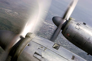
Photo copyright Rod Digney (Viscount Network) - used with permission
This accident revealed the vulnerability to drag limiting devices with the authority to affect the thrust on more than one engine. The primary role of an autofeather system is to quickly reduce the drag associated with a failed engine, without requiring fight crew action. However, if more than one engine automatically feathers, the effect on airplane performance is sufficiently detrimental that an accident may be the result. Common cause events - multiple bird ingestions, ice ingestion, etc., may affect more than one engine. Subsequent propeller system designs incorporated safeguards (e.g., electrical relays) that prevented automatic feathering of more than one engine, with the intent of limiting thrust loss to not more than one engine.
Acknowledgement
The FAA acknowledges the Viscount Network, a Virtual Museum, for their support and assistance, which greatly aided in development of this accident module.
The Civil Aeronautics Board accident report did not contain any specific findings, but rather provided a detailed analysis of the circumstances of the accident. The probable cause was determined to be:
The Board determines that the probable cause of this accident was the delayed arming of the engine ice protection systems while flying in icy conditions, resulting in the loss of engine power and attendant electrical energy required to unfeather the propellers and relight sufficient engines to maintain flight.
The accident report is available at the following link: (CAB Accident Report)
The Civil Aeronautics Board did not issue any formal recommendations relative to this accident. However, based on facts established during the investigation, on July 14, 1960, the CAB issued a letter to the Federal Aviation Agency advising that Capital Airlines was not yet following proper procedures related to the use of the ice protection system.
The manufacturer had issued a change to procedures for use of the ice protection system to all Viscount operators 19 months prior to the accident. At the time of the accident, Capital Airlines had not incorporated this change into the normal or emergency procedures of their flight or training manuals, and many pilots at Capital Airlines were not aware of the change to the procedure. The July 14 letter to the FAA was intended to insure that the most up to date procedures were adopted and followed by the airline.
The Viscount was designed and constructed by Vickers Armstrongs in England. The Type 745D Viscount was approved by the United States Civil Aeronautics Administration (CAA) under Civil Air Regulation (CAR) 10 on February 23, 1956. CAR 10 recognized and accepted the British Civil Airworthiness Requirements as being equivalent to the U.S. Civil Air Regulation (CAR) 4b.
Vickers Armstrongs Viscount
Engine Isolation
CAR 4b.401 Engines
This rule required isolation between engines, and engine systems such that a failure affecting one engine will not prevent the safe operation of the remaining engines, or require immediate action by the crew.
Engine Ice Protection
CAR 4b.461 Induction system anti-icing and de-icing provisions
The Viscount was one of the first turbine (turbopropeller) powered airplanes in aviation. As such, induction ice protection was not addressed by the regulations in affect at the time. Turbine induction ice protection was addressed by rule changes that occurred in 1958, after certification of the Viscount. A consideration of delayed system actuation did not exist at the time of Viscount certification.
Rolls-Royce Dart
Engine Ice Protection
CAR 13.210 Fuel and Induction System
This regulation required that the engine air induction system be protected against the accretion of ice.
The Viscount was among the first turbine powered aircraft in commercial service. The new technology exposed many vulnerabilities that had not been envisioned by the existing regulations. Environmental hazards such as birds, ice, and hail were soon discovered to represent hazards for turbine engines that had not been hazardous for reciprocating powered airplanes. It was also discovered that the windmilling drag of turbopropeller airplanes was higher than for piston powered airplanes, and had a more adverse effect on airplane performance, especially during takeoff and landing/go-around. This resulted in a focus on rapidly acting automatic feathering systems in order to minimize the performance impacts. This accident exposed the additional vulnerability of allowing autofeather systems to operate independently and affect all engines simultaneously.
- The Viscount was not adequately protected from ice ingestion resulting from a delayed actuation of the engine ice protection system.
- The airplane did not adequately address engine isolation requirements in that a multiple engine common cause event could result in automatic feathering of all engines.
- It was not anticipated that all four engines could flame out simultaneously and all four propellers feather at the same time making relight and recover of controlled flight more difficult.
- Rapidly reacting automatic feathering systems were a safety enhancement, allowing improved airplane performance, relative to a windmilling propeller, following an engine failure.
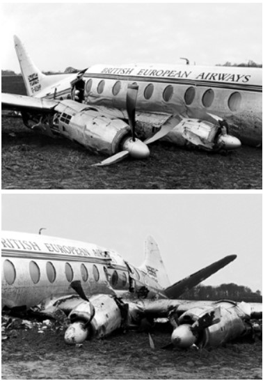
Vickers Viscount 802, G-AOHP, Ballerup, Denmark
Copyright Richard Stanton (Viscount Network) - used with permission
On November 17, 1957, while on approach to Copenhagen, Denmark, a Vickers Viscount model 802, operated by British European Airways, lost power on three engines. As the aircraft descended through 4000' it entered a layer of stratus cloud where the outside temperature was -2°C. Eleven minutes after arriving over the approach holding point, the airframe de-icing was turned on. Soon thereafter, the aircraft swung to the left due to a loss of power on the number 1 engine. The aircraft was turned back on course when it began to lose altitude rapidly. It was then realized that number 3 and 4 engines had also failed. The aircraft descended at 600 feet per minute with power from the remaining number 2 engine. At 1,500' the aircraft broke out of the clouds and was directed toward an emergency landing sight. An emergency landing was made at 0403 14 miles northwest of the airport at Copenhagen.
Probable Cause of the Accident
"The cause of the engine failures, which brought about the accident, lay in the accumulation of ice on the engine cowlings which, because of malfunctioning of the de-icing system was allowed to build up before being dislodged. Passage of the lumps of ice through the engines caused partial flame out, which produced sufficient loss of power to initiate the auto-feathering and thus to stop the engines."
View British European Airways Corporation, Vickers Viscount 802, G-AOHP accident report.
Turbine Engine Induction Ice Protection-Delayed Actuation
Regulatory
This accident, and other accidents/incidents involving airplanes of the same era, identified a need for a more comprehensive approach to turbine engine ice protection. 14 CFR part 25 includes icing envelope definitions in Appendix C, and further addresses engine induction system icing in 14 CFR 25.1093, and 14 CFR 33.68.
Part 25 Appendix C identifies icing conditions, based on liquid water content and water droplet size in which the airplane and airplane/engine combination must be capable of operating safely.
14 CFR 25.1093 and a companion regulation 14 CFR 33.68 identify the requirements for turbine engine operation in the icing conditions of Appendix C, and for which the engines must remain free of ice accumulations that would adversely affect engine operation or cause a serious loss of power/thrust.
However, neither of these regulations addressed the effects of delayed ice protection system activation, which had been a primary cause of the Capital flight 20 accident. On the Viscount, the ice protection system was effective, insofar as it was activated upon entry into icing conditions. Recognition of a needed margin from system “OFF” to system “ON” was generally applied via policies, and on a case by case basis during airplane certification programs of the 1960’s and 70’s.
An example of delayed actuation testing conducted on a Boeing 777 and 737 is below. This video was provided by the Boeing Company.
Photos copyright The Boeing Company – used with permission
Advisory Circulars
FAA Advisory Circular (AC) 20-147, Turbojet, Turboprop, and Turbofan Engine Induction System Icing and Ice Ingestion provides the criteria for certification of engine and airplane/engine combinations in the icing conditions of part 25, Appendix C. In particular, delayed engine ice protection system activation is addressed relative to resultant consequences, and certification demonstration conditions. The AC defines a “nominal” delay of two minutes as from entry into icing condtions until activation of the system as the reasonable time delay for certification.
Turbopropeller Autofeather – Engine Isolation
14 CFR 25.901 and 25.903 specify essentially the same design criteria as CAR 4b.401. The Viscount did not adequately provide engine isolation to prevent multiple engine automatic feathering resulting from a single encounter. Though no specific regulatory changes regarding multi-engine autofeather have been adopted since the Capital flight 20 accident, industry, and authorities have applied the knowledge gained relative to this vulnerability.
Airplane Life Cycle
- Design / Manufacturing
Accident Threat Categories
- Inclement Weather / Icing
- Lack of System Isolation / Segregation
Groupings
- N/A
Accident Common Themes
- Human Error
- Unintended Effects
Unintended Effects
Drag limiting devices, such as an automatic feathering system, provide a performance benefit for an airplane. Automatic feathering following an engine failure quickly removes the additional drag resulting from a windmilling engine and reduces the workload of the flight crew during critical phases of flight, such as takeoff. In this accident, all engines were automatically feathered following ice ingestion. Automatic feathering on all engines led to a total thrust loss and required the flight crew to focus on restarting all engines to remain airborne. Isolation of the autofeathering system to inhibit its functioning on more than one engine would have allowed the crew to systematically address each engine and determine if, following the automatic feathering of a single engine, other engines required shutdown/feathering, or could continue to operate.
The CAB investigated the history of Rolls-Royce Dart engines inadvertently shutting down in flight over 11 million flight hours. There were 18 reported cases involving 18 airplanes in which multiple loss of engine power occurred. The reasons were late selection of anti-icing equipment or ice formation in the fuel lines and / or the presence of a large amount of water in the fuel system. In all the instances where anti - ice selection was delayed the engines recovered normally or were relit.
Technical Related Lessons
Propulsion systems must be arranged and isolated so that engine malfunctions, including multiple engine common cause events, such as ice or bird ingestion, do not activate systems that jeopardize thrust on more than one engine. (Threat Category: Lack of System Isolation/Segregation)
- This accident was initiated by ice ingestion on multiple engines following the delayed actuation of the engine ice protections systems. Ice-ingestion led to a thrust reduction and automatic feathering on all four engines. Had proper system isolation been implemented on this design, automatic feathering would only have occurred on a single engine, protecting the ability of the other engines recover, and reestablish thrust. A significant population of multi-engine events led to engine self-recovery, without crew action. However, in the event that an engine did not self-recover, manual feathering was still available, if required. In this accident, the actuation of automatic feathering on all engines inhibited the flight crew’s ability to respond to the situation in any means other than to concentrate on unfeathering the propellers and restarting the engines that had shut down.
Propulsion systems should be capable of operation in icing conditions for a nominal period of time with the ice protection system not operating, followed by activation of the system. Delayed activation should not result in a level of engine damage that prevents the continued safe flight and landing of the airplane (Threat Category: Inclement Weather/Icing)
- In this accident, the airplane was in icing conditions for a sufficient period of time that, according to the investigation, an ice buildup of ¼ to ½ inch accumulated on the engine inlets. Once activated by the crew, the ice protection system caused the accumulated ice to release from the inlets and be ingested into the engines. The ice ingestion led to thrust reduction, or flameout, and subsequent automatic feathering on all four engines. The crew was unable to restart all four engines and restore a level of thrust needed to remain airborne. Subsequent to the accident, regulatory authorities required that the airplane be capable of operation for at least two minutes prior to activation of ice protection systems. The resulting consequence of this delayed activation may not pose a threat to continued safe flight and landing. In the case of a turbopropeller airplane, a nominal delay in actuation of the engine ice protection system may result in the automatic feathering of a single propeller, but the fact that propulsion systems are required to be isolated would limit automatic feathering to a single engine.
Common Theme Related Lessons
Propulsion systems intended to protect the airworthiness of the airplane should be arranged in a manner that preserves engine isolation, and limits the authority of protection systems to affecting no more than one engine. (Common Theme: Unintended Effects)
- Drag limiting devices, such as an automatic feathering system, provide a performance benefit for an airplane. Automatic feathering following an engine failure quickly removes the additional drag resulting from a windmilling engine and reduces the workload of the flight crew during critical phases of flight, such as takeoff. In this accident, all engines were automatically feathered following ice ingestion. Automatic feathering on all engines led to a total thrust loss and required the flight crew to focus on restarting all engines to remain airborne. Isolation of the autofeathering system to inhibit its functioning on more than one engine would have allowed the crew to systematically address each engine and determine if, following the automatic feathering of a single engine, other engines required shutdown/feathering, or could continue to operate.