
McDonnell Douglas MD-88
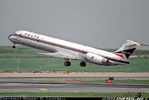
Photo copyright Robert M. Campbell - used with permission
Delta Air Lines Flight 1288, N927DA
Pensacola, Florida
July 6, 1996
On July 6, 1996, at 1424 central daylight time, a McDonnell Douglas MD-88, N927DA, operated by Delta Air Lines Inc. as Flight 1288, experienced an engine failure during the initial part of its takeoff roll on runway 17 at Pensacola Regional Airport in Pensacola, Florida. Uncontained engine debris from the front compressor, front fan hub of the No. 1 (left) engine penetrated the aft fuselage. Two passengers were killed, and two others were seriously injured. The takeoff was rejected, and the airplane was stopped on the runway. The airplane had been destined for Hartsfield Atlanta International Airport in Atlanta, Georgia and included 137 passengers and five crew. The National Transportation Safety Board (NTSB) determined that the probable cause of this accident was the fracture of the left engine's front compressor fan hub, which resulted from the growth to failure of a fatigue crack. A causal analysis undertaken as part of the accident investigation revealed the following: The crack initiated from an area of altered microstructure that was created during a hole drilling process by Volvo for Pratt & Whitney. The anomaly went undetected by Volvo's production inspection system.

Photo copyright Paul Robbins - used with permission
Accident Details
On July 6, 1996, at 1424 central daylight time, a McDonnell Douglas MD-88, N927DA, operated by Delta Air Lines Inc. as Flight 1288, experienced an engine failure during the initial part of its takeoff roll on runway 17 at Pensacola Regional Airport (PNS) in Pensacola, Florida. Flight 1288 was cleared for takeoff at 1423. The first officer, who was the pilot flying, advanced the throttles and called for the autothrottles to be set. The throttles were advancing in the autothrottle mode when the flight crew heard a "loud bang," followed by the loss of cockpit lighting and instrumentation. Passengers and flight attendants in the rear of the cabin described experiencing a "concussion or blast-like sensation." The captain took control of the airplane and retarded both throttles to idle. He applied manual brakes and brought the airplane to a gradual stop on the runway. There were no cockpit indications or warnings of fire. The flight data recorder indicated that the airplane had reached a speed of about 40 knots when the left engine failed. Uncontained engine debris from the front compressor front fan hub of the No. 1 (left) engine penetrated the aft fuselage. Two passengers were killed, and two others were seriously injured.
- NTSB Docket Photo
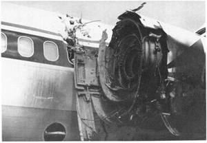
Damage to Airplane and Engine
The aft fuselage and interior of the airplane in the vicinity of the No. 1 engine were substantially damaged by debris from the engine. A total of 16 holes, punctures, or tears were documented in the left fuselage skin. Several large holes and tears were found adjacent to seat row 37. Seven exit holes, punctures, and tears were documented in the right fuselage skin just forward of row 37. Most of the wires in the wire bundle located on the right side of the fuselage were severed. Of the 154 wires in the bundle, 146 had been severed. No evidence of penetrations existed below the floor level on either side of the fuselage. The cabin interior was substantially damaged near seat row 37, next to the left engine. Debris from the left engine's fan hub and fan blades had penetrated the left cabin wall and overhead bin vertically from the passenger window, through the overhead bin, and ceiling panel. Engine fan components had also pierced the side and ceiling of the right cabin wall. The No. 1 engine, a Pratt & Whitney JT8D-219 turbofan, was heavily damaged.
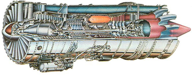
Airplane Engines
The airplane was equipped with two Pratt & Whitney JT8D-219 turbofan engines. The JT8D-200 series engine is an axial-flow front turbofan with a 14-stage split compressor, a 9-can combustion chamber, and a split, 4-stage reaction impulse turbine. The No. 1 (left) engine, S/N 726984, had a total operating time of 7,371.7 hours and 5,905 operating cycles since new. Delta was the original operator of the engine. The engine had been installed on the accident airplane on January 1, 1996 and had since then accumulated 1,528 hours and 1,142 cycles. It had been removed from another Delta airplane on December 21, 1995, following a report of "smoke in cabin." The problem had been identified as an oil leak in the compressor section, and a carbon seal was replaced.
Left Engine Compressor Fan Hub
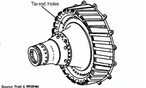
The left engine's fan hub, S/N R32971, had a total time of 16,542 hours and 13,835 cycles at the time of the accident. At the time of the engine's installation on the accident airplane in January 1996, the hub had accumulated 12,693 cycles. The titanium fan hub was forged by Ladish Company in Milwaukee, Wisconsin, and machined, finished, and inspected for Pratt & Whitney by Volvo Aero Corporation in Trollhattan, Sweden, in January 1989, according to Pratt & Whitney records. The service life of this type of fan hub is limited to 20,000 cycles. The hub consisted of a disk forging that held 34 fan blades in dovetail (interlocking joint) slots. The aft end of the hub attached to the stage 1.5 disk with 24 tierods that passed through .5175-inch diameter tierod holes drilled in the hub web just inside of the dovetail slots. The 2.91-inch deep tierod holes were located around the circumference of the hub bore and alternated with 24 smaller diameter stress redistribution (SR) holes. The fan hub was forged from a titanium-based alloy containing 6 percent aluminum and 4 percent vanadium (Titanium 6AL-4V).
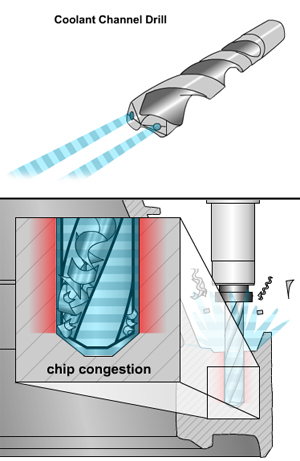
Volvo's Tierod Hole Drilling Process
View Delta Flight 1288 Accident Animation below. (Note: It is recommended that this animation be viewed prior to reading the remainder of the Overview.)
The tierod holes in the accident hub were created using a four-step process: the hole was drilled, bored in two steps, and then honed. Three tools were used to create tierod holes: a drill, a boring bar, and a hone. The 24 tierod and SR holes on the accident hub were drilled using a computer controlled coolant channel drill, which was designed to use coolant streams to flush titanium chips from the hole during a "one-pass" or single-plunge drilling process. The coolant channel drill used on the accident hub was a conventional pattern twist drill with tungsten carbide cutting-edge inserts. The .480 inch diameter drill had an internal conduit for coolant to flow down the drill core and enter the hole being drilled behind two carbide cutting edges. The coolant served as a lubricant and flushing agent to remove chips from the hole. The flushing was critical because titanium chips can be easily compacted in hole-drill interface areas, and can cause friction and elevated temperatures in holes.
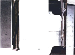
Note coolant hole in drill tip
The previous drilling process used for the manufacture of fan hubs had used a standard drill that was removed every .20 inches during drilling. This is described as a "pecking process", the purpose being to purge chips from the hole. This is accomplished by removing the drill tool and applying high pressure coolant to the work interface. The fundamental reason for using a pecking hole drilling operation for the JT8D-200 Series fan hub is due to the disc having a large cross section of over three inches. This results in a very high hole length to diameter ratio of 6 (3 in / .5 in = 6) which has historically been shown as highly prone to chip congestion.
Subsequent to the drilling operation which drills the hole to a .480-inch diameter, the hole was enlarged by a boring operation. The first boring step enlarged the hole to .508 inch diameter, using the same type of spindle that held the drill. A second boring step enlarged the hole to .516 inch. The holes were then finished on a second machine that uses a boron nitride hone with a lubricant or honing oil, resulting in a finished diameter of .5175 inch. The difference between the diameter of the coolant channel drill and the finished hole was about .0375 inch. The total radial depth of the material removed after drilling was about .0188 inch.
Metallurgical Effects of Abusive Machining
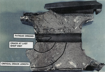
The fractured components of the accident fan hub were examined in the National Transportation Safety Board's materials laboratory. The fan hub had fractured radially in two places. One of the radial fractures contained a fatigue crack that originated at two locations on the inboard side of a tierod hole.
Metallurgical examination of the surface of the hole wall revealed an area in which the surface finish was darker than the surrounding area at each fracture origin. The hole surface in the darker areas showed evidence of circumferential machining marks consistent with marks that would be left by the boring operation performed during the part's manufacture. There was no indication of honing in the darker areas. The remainder of the hole wall surface outside the darkened surface finish areas showed a cross-hatched pattern consistent with marks that would be left by the honing operation. Magnified examination of the hole wall in the darker areas also showed numerous small parallel surface cracks (ladder cracks) aligned with the longitudinal axis of the hole.
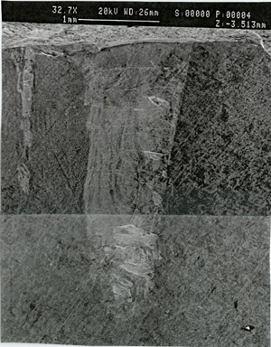
View depicts numerous small parallel surface cracks
(ladder cracks) aligned with the longitudinal axis of the hole.
A scanning electron microscope (SEM) examination of the fracture face in the origin areas showed evidence of overstress to a depth of about 0.002 inch adjacent to the hole wall. The overstress fracture region was followed by an area about 0.006 inch deep that contained fracture features consistent with a fast-propagating fatigue crack. From a depth of 0.006 inch to the end of the fatigue region, striations were found consistent with a slower propagating fatigue crack. Approximately 13,000 fatigue striations were found in the fatigue fracture region, roughly equivalent to the number of the hub's flight cycles.
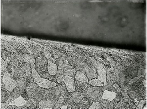
Normal grain structure is present away from hole with
distorted grain structure located at the hole edge.
Metallurgical examination of the cross section of one of the fatigue origins showed three zones of altered microstructure adjacent to the hole wall surface corresponding to the darkened surface finish areas on the hole wall. The microstructural zone closest to the hole wall surface was about 0.002 inch deep (the same as the overstress depth). This zone was heavily layered with recrystallized alpha grains, indicating that the surface temperature had reached at least 1200°F, which is the minimum recrystallization temperature for titanium.
The second zone of altered microstructure was from 0.002 inch to 0.006 inch from the wall surface (about 0.004 inch thick). The microstructure in this zone consisted of heavily deformed alpha and beta grains elongated parallel to the surface. Below this area, to a depth of about 0.010 inch from the surface of the hole, was a third zone where the microstructure was distorted in a curved pattern, consistent with the metal having been deformed by bearing pressures from a rotating tool during the manufacturing process.
Pratt & Whitney Engineering Source Approvals
from Delta Flight 1288 Accident Animation
Pratt & Whitney Engineering Source Approval (ESA) is the manufacturing engineering requirement to verify that a component manufactured to a specific process and drawing requirement meets design integrity, and ultimately assures that no critical process is detrimental to achieving this integrity. ESA requirements may include: part cutups, metallurgical examinations, manufacturing sequence sheets, Critical Process technical plans, first article and selected process validation tests. ESA is a multi-disciplined function that requires a skill mix that includes Design Engineering, Manufacturing Engineering, Materials Engineering and Quality Assurance.
Pratt & Whitney records indicated approval of Volvo's request to use the coolant channel drill (rather than a standard drill) on February 11, 1988. The Pratt & Whitney Process Approval Record (PAR) noted that the request was characterized as an "insignificant change." The change was approved by the ESA function without metallurgical evaluation requirements because changes in drilling operations were classified as "insignificant" by Pratt & Whitney since subsequent material removal (in the boring and honing phases) had been accomplished to a depth of at least .010 inch. Pratt & Whitney indicated that generally, in the machining of titanium holes, if greater than ten thousandths were removed in subsequent operations, any potential adverse effects from the drilling process would be eliminated.
Special FAA Audit of Pratt & Whitney
Following the accident, the FAA conducted a "special quality system audit" at Pratt & Whitney from July 29 through August 2, 1996. The special audit noted that Pratt & Whitney's ESA function requires that a PAR be issued for "significant changes." The FAA audit report noted that "significant changes include new tooling, change in sequence of operations, a change in any process which could result in cracking, or change of process location within a plant."
Noting Volvo's request for the drill process change, the FAA audit stated that "several PARs were observed in which tooling was changed and/or operation sequence, and that these approvals were classified as insignificant." Subsequent to this audit, Pratt & Whitney changed this procedure, to require that all changes related to hole drilling be considered "significant" and reviewed according to requirements for that category of change.
Special FAA Audit of Volvo Flygmotor

Following the accident, the FAA conducted a "special quality system audit" at Volvo from August 13 through August 16, 1996. The audit issued a report that included the following issues:
- At the time the accident hub was produced, the JT8D-219 fan hub scrap rate was approximately 11%. This scrap rate was considered relatively high within the turbine engine manufacturing industry.
- Fan hub tiebolt hole drilling was considered an "insignificant" process, therefore no metallurgical evaluation was performed for machined feature microstructure. Metallurgical evaluation was performed for the boring and honing processes only.
- An ESA review was conducted of all change activity associated with the tiebolt hole drilling process. The review identified 12 changes in tooling or processes from 1984 to 1996.
- All 12 changes were classified as "insignificant" and thus never received a high level of engineering scrutiny.
- A detailed review of the 12 changes revealed a drill process change to a coolant channel drill that resulted in substantial deposits, smearing and imbedding of titanium onto the drill.
- It was concluded that the coolant channel drill process combined with localized loss of coolant, and chip packing overheated the material and created the altered microstructure and ladder cracking in the accident fan hub.
- Per ESA requirements for tierod holes, Volvo was required to submit metallurgical samples of material machined with sharp tooling as well as samples machined just prior to tool resharpening. Neither Pratt & Whitney nor Volvo could provide evidence of metallurgical samples of material machined just prior to tool resharpening, or data for tool replacement/resharpening intervals. The ESA requirements for part sampling were intended to assure continuous manufacturing integrity. As tooling becomes worn, the sampling process is considered vital to confirmation of manufacturing quality and consistency.
- Volvo manufacturing records indicated that there were Blue Etch Anodize inspection "indications" at the exact location of the two fatigue crack origins that were found during the post-accident metallurgical investigation. According to Volvo, the indications did not match any of the templates used by Volvo, at the time, to identify anomalies, and were therefore not considered blue etch indications. These two indications were strictly an observation made by the inspector regarding the hole surface. There was no notation of a Blue Etch Anodize indication of a defect in Volvo manufacturing records relating to the accident hub. In the subsequent visual inspection, the inspector used a sharp point stylus to check for geometric anomalies, and none were found. It was determined during the audit that a stylus would not have been effective in evaluating a blue etch indication. Investigators concluded that a geometric inspection method, such as using a stylus, would not be effective in identifying metallurgical anomalies, and that the fan hub should have been subjected to further metallurgical evaluation
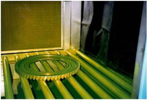
Post-Manufacturing Inspection
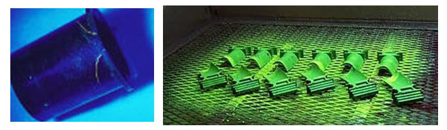
Investigators identified several post manufacturing inspection processes for completed hubs that were performed at Volvo. These inspections included: dimensional and visual inspections, Fluorescent Penetrant Inspection (FPI) and Blue Etch Anodize (BEA) inspection. The dimensional inspection checks the location, concentricity, diameter, and perpendicularity of holes. The visual inspection examines the surface finish and looks for evidence of residual machine marks. The FPI checks the surface of the material for physical defects such as cracks, voids, or metal porosity. The BEA inspection process, which is unique to titanium, visually inspects the surface after anodizing (the surface is electro-chemically oxidized), to check for anomalies associated with microstructure changes in the metal.
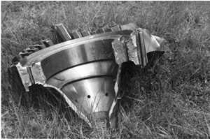
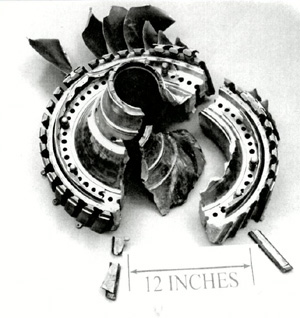
Note: hub failed through tierod holes
The investigation determined that the accident fan hub had two documented nonconformance notations, as it progressed through the manufacturing process:
- Following the drilling process, the drill operator noted two holes that contained "chatter marks". These "chatter marks" were no longer noted after completion of boring and honing.
- The BEA inspector further noted, during his inspection of the accident hub, manufacturing marks in a hole located 180 degrees relative to the serial number marking.
This was the same tierod hole analyzed by the safety board after the accident. Manufacturing records provided no further description of the accident hub manufacturing marks, or where they were located in the hole. Subsequent inspections determined that the fan hub met Pratt & Whitney's manufacturing criteria, and it was sent to Pratt & Whitney for installation.
The investigation determined that inspection notations had been made to alert visual inspectors to the surface condition. However, the indication did not match any of the templates used by Volvo to identify anomalies, and was not characterized as a blue etch indication, but was rather an observation made as to the surface condition. Finally, manufacturing records did not contain a BEA notation of a defect on the accident hub.
In-Service Inspections
The investigation established that, as a "safe life" or "life-limited" part, the fan hub was designed and certified to operate safely for its total design life of 20,000 cycles without inspection, unless it was removed from the engine. Once an engine entered operational service, Fluorescent Penetrant, and visual inspections were conducted on fan hubs at the Delta overhaul facility only if they were removed during engine overhaul or disassembly.
Following the accident, the FAA conducted a technical review of Delta's FPI process at its Atlanta, Georgia, maintenance facility.
In the report of the review team's findings, "Technical Review of Fluorescent Penetrant Process Delta Air Lines Inc.," it was concluded that, based on reliability data collected by the Nondestructive Testing Information Analysis Center (NTIAC), "a crack of this size (a total surface length of 1.36 inch on the accident hub) should be detectable with a probability of detection (POD) and confidence level both exceeding 95 percent." Data compiled by the NTIAC also indicated that the minimum reliable detection length for FPI is about 0.10 inch.
The findings of the FAA review included:
- "There is no assurance that the material received by the nondestructive inspection organization for FPI processing was clean enough for an adequate FPI.
- Engine part cleaning personnel receive on-the-job-training (OJT), with no formal classroom training. The team noted that sensitivity to the criticality of the engine components and the end purpose for which these components were being cleaned was not provided as part of the OJT (critical rotating versus static, general visual inspection versus nondestructive inspection).
- The solvent on the production floor the morning of August 14, 1996, was badly contaminated with fluorescing material.
- Visible trash and debris were under the transport rollers utilized on the FPI line. Since there are no protective covers over the tanks containing the FPI process materials, similar trash and debris is expected in the FPI material.
- The transport rings utilized for parts holding during the FPI process became easily contaminated with fluorescent material. One inspector was noted having a difficult time inspecting the inside of a hole because of the high fluorescent background from the transport ring visible through the hole. He tried shielding the ring from view with his glove, but it also was contaminated with fluorescent material.
- One inspector was noted touching the component to be inspected, and smearing the inspection area, before inspecting it.
- There appears to be no uniform way of handling and indexing components during evaluation in the inspection booth."
Fluorescent Penetrant Inspection of turbine engine blades (right)
The FAA report noted that during, and following the inspection team's on-site evaluation, Delta initiated positive and responsive actions to the team's recommendations. Personnel involved in inspections now receive enhanced training related to inspection preparation, especially of critical parts. Also, standards were developed with engine manufacturers for cleaning of parts prior to inspection.
Following are select findings specific to the fan hub failure excerpted from the NTSB report:
- Some form of drill breakage or drill breakdown, combined with localized loss of coolant and chip packing occurred during the drilling process, creating the altered microstructure and ladder cracking in the accident fan hub.
- Fatigue cracks initiated from the ladder cracking in the tierod hole and began propagating almost immediately after the hub was put into service in 1990.
- Although the altered microstructure in the accident hub tierod hole was detectable by blue etch anodize inspection methods, Volvo did not identify it as rejectable because the appearance of the tierod hole did not match any of the existing inspection templates showing rejectable conditions.
- Although the additional templates will assist blue etch anodize inspectors in detecting potential defects similar to the one that existed on the accident hub, this accident suggests that there may be additional rejectable conditions that have not yet been identified.
- Drilling damage in this accident hub extended much deeper into hole sidewall material than previously anticipated by Pratt & Whitney.
- The crack was large enough to have been detectable during the accident hub's last fluorescent penetrant inspection at Delta.
- Significant questions exist about the reliability of flash drying in removing water from cracks.
- Better techniques are needed to ensure the fullest possible coverage of dry developer powder, particularly along hole walls.
- Although it could not be conclusively determined whether this played a role in the nondetection of the crack in the accident hub, the absence of a system that formally tracks the timing of the movement of parts through the fluorescent penetrant inspection process was a significant deficiency.
- Fluorescent penetrant inspection indications remain vulnerable to manual handling, and fixtures used to support the part during inspection may obstruct inspector access to areas of the part.
- No personal or physical factors would have prevented the FPI inspector from detecting a visible crack in the accident hub.
- A low expectation of finding a crack in a JT8D-219 engine fan hub might have caused the FPI inspector to overlook or minimize the significance of an indication.
- Because of the potentially catastrophic consequences of a missed crack in a critical rotating part, testing methods that evaluate inspector capabilities in visual search and detection and document their sensitivity to detecting defects on representative parts are necessary.
- Delta's nondetection of the crack was caused either by a failure of the cleaning and fluorescent penetrant inspection processing, a failure of the inspector to detect the crack, or some combination of these factors.
- Manufacturing and in-service inspection processes currently being used do not provide sufficient redundancy to guarantee that newly manufactured critical rotating titanium engine parts will be put into service defect-free and will remain crack-free through the service life of the part. Further, all critical rotating titanium engine components are susceptible to manufacturing flaws and resulting cracking and uncontained engine failures that could potentially lead to catastrophic accidents.
The probable cause was identified as:
The National Transportation Safety Board determines that the probable cause of this accident was the fracture of the left engine's front compressor fan hub, which resulted from the failure of Delta Air Lines' fluorescent penetrant inspection process to detect a detectable fatigue crack initiating from an area of altered microstructure that was created during the drilling process by Volvo for Pratt & Whitney and that went undetected at the time of manufacture. Contributing to the accident was the lack of sufficient redundancy in the in-service inspection program.
The NTSB identified 30 findings for this accident. The complete list is available at the following link: NTSB Findings
The entire NTSB report (NTSB/AAR-98/01) can be viewed at the following link: NTSB Report
Following are select NTSB recommendations specific to the fan hub failure excerpted from the NTSB report:
- Form a task force to evaluate the limitations of the blue etch anodize and other post manufacturing etch processes and develop ways to improve the likelihood that abnormal microstructure will be detected. (A-98-09)
- Inform all manufacturers of titanium rotating engine components of the potential that current boring and honing specifications may not be sufficient to remove potential defects from holes and ask them to reevaluate their manufacturing specifications and procedures with this in mind. (A-98-10)
- Establish and require adherence to a uniform set of standards for materials and procedures used in the cleaning, drying, processing, and handling of parts in the fluorescent penetrant inspection process. In establishing those standards, the FAA should do the following:
- Review the efficacy of drying procedures for aqueously cleaned rotating engine parts being prepared for fluorescent penetrant inspections; (A-98-11)
- Determine whether flash drying alone is a sufficiently reliable method; (A-98-12)
- Address the need to ensure the fullest possible coverage of dry developer powder, particularly along hole walls; (A-98-13)
- Address the need for a formal system to track and control development times; (A-98-14)
- Address the need for fixtures that minimize manual handling of the part without visually masking large surfaces of the part. (A-98-15)
- Require that all heavy rotating titanium engine components (including the JT8D-200 series fan hubs) receive appropriate nondestructive testing inspections (multiple inspections, if needed) based on probability of detection data at intervals in the component's service life, such that if a crack exists, but is not detected during the first inspection, it will receive a second inspection before it can propagate to failure; assuming that a crack may begin to propagate immediately after being put into service, as it did in the July 6, 1996, accident at Pensacola, Florida, and in the July 19, 1989, United Airlines accident at Sioux City, Iowa. (A-98-19)
- Require, as an interim measure, pending implementation of Safety Recommendation A-98-19, that critical rotating titanium engine components that have been in service for at least 2 years receive a fluorescent penetrant inspection, eddy current, and ultrasonic inspection of the high-stress areas at the engine's next shop visit or within 2 years from the date of this recommendation, whichever occurs first. (A-98-20)
The complete text of the NTSB recommendations is available at the following link: NTSB Recommendations
JT8D-219 CERTIFICATION BASIS: FAR 33 effective February 1, 1965, as amended by 33-1, 33-2, 33-3, 33-4, 33-5, 33-6 and FAA Exemption Number 2897-1.
Specific relevant engine regulations from FAR part 33: 14 CFR 33.15 (Materials), 14 CFR 33.19 (Durability) and 14 CFR 33.70 (Engine life-limited parts) (Note, 33.70 replaces 33.14)
Relevant to Production Certification and conformance to type design: 14 CFR 21.143 (Quality control data requirements; prime manufacturer) and 14 CFR 21.165 (Responsibility of holder)
Relevant to maintenance and inspection: FAR part 121, Subpart L (Maintenance, Preventive Maintenance, and Alterations). Specifically, 14 CFR 121.367 (Maintenance, preventive maintenance, and alterations programs) and 14 CFR 121.373 (Continuing analysis and surveillance)
For critical holes produced with multiple processes (drilling, boring and honing) it was generally accepted, based on metallurgical data, that any material flaws introduced by the drilling process would be removed by the subsequent boring and honing processes. This practice proved flawed for the production of the Pensacola JT8D-219 hub when material anomalies introduced by drilling extended much deeper into the hole sidewall than previously anticipated by Pratt & Whitney and were not completely removed by the boring and honing processes.
The fan hub is a "safe life" or "life-limited" part and was certified by the FAA, based on Pratt & Whitney engineering data, to operate safely for its total design life of 20,000 cycles. The hub does not require inspection unless it is removed from the engine. FPI and visual inspections were conducted on fan hubs at the Delta overhaul facility only if they were removed during engine overhaul or disassembly. Delta stated that with a "safe life" part, it is assumed that the part is defect-free on delivery and inspection techniques are selected to find normal wear and tear and abuse not pre-existing damage. Delta also stated if they were required to assume pre-existing damage was present then an alternate inspection technique such as eddy current or ultrasonic would have been employed. Safe life assumes the part will operate safely throughout its design life even without an inspection. The FAA fundamentally ascribed to this position at the time of the accident. However, the FAA has changed its assumption that Life Limited Parts (LLP's) are delivered defect free, and as such, now mandates repetitive inspection (Enhanced Engine Inspection Initiative) of all LLP's at all levels of exposure.
Failure of the engine front fan hub, resulting in the release of high energy debris that struck the airplane and its occupants.
Producers of high energy rotating engine components are adequately validating critical manufacturing processes such that robust tooling and process parameters are utilized to assure that no manufacturing anomalies are introduced and that components comply with the design intent.
At the time the Pensacola Fan Hub was designed, the engine industry lifing analysis process assumed defect free material 100% of the time. AIA/FAA introduced probabilistic design analysis tools that assumed defect distribution based on defect rates derived from the Rotor Manufacturing Project Lessons Learned Database.
Producers of high energy rotating engine components employ NDT methods that are capable of detecting both geometric and non-geometric (metallurgical) manufacturing induced anomalies.
Airline maintenance NDI personnel are adequately trained, and NDI procedures are adequately designed and implemented such that detectable cracks in critical rotating engine parts will be detected.
Original equipment manufacturers (OEM) are providing adequate oversight of critical manufacturing process validation functions, including critical part and process suppliers, such as machiners, forgers, melters, etc. or first, second or third tier suppliers.
FAA is providing oversight of the OEMs to ensure that OEM oversight of suppliers and vendors is adequate.
At the time of the Pensacola accident, there was an industry wide initiative underway for the purpose of studying causes of turbine engine uncontained failures and identifying areas where improvements could be made. This initiative led to the development of the Aerospace Industry Association Rotor Manufacturing Subcommittee Lessons Learned Database to identify safety precursors associated with turbine engines.
Other engine manufacturers have also experienced rotor failures associated with abusive machining of hub and disc bolt holes. Examples of some of these failures include:
- JT8D-7B engine fan hub uncontained fracture on Pan American World Airways 727 on takeoff in Miami on February 17, 1982. The titanium fan hub failed due to fatigue cracking initiating from an area of abusive machining.
- CF6-6 engine fan hub uncontained fracture on United Airlines DC-10, Sioux City, Iowa on July 19, 1989. The titanium fan hub failed due to fatigue cracking initiating from a Type I hard alpha metallurgical defect on the surface of the fan hub bore.
- CF6-50C2 engine HPC stage 3-9 spool uncontained fracture on an Egypt Air A300-B4 during takeoff roll in Cairo, Egypt in 1995. The stage 6 portion failed due to fatigue cracking initiating from a nitrogen stabilized hard alpha inclusion located on the aft side of the disk web.
At the time the accident hub was produced, the JT8D-219 fan hub scrap rate at Volvo was approximately 11%. This was considered by investigators to be an extremely high scrap rate. In addition, it was learned that Volvo had introduced 12 process changes to the hole drilling operation.
14 CFR 33.70, Engine life-limited parts.
While the requirement to establish the maximum allowable number of flight cycles for each engine life-limited part previously existed, this new rule also requires the establishment of an engineering plan, a manufacturing plan and a service management plan to help assure the integrity of each engine life-limited part.
14 CFR Part 193, Protection of voluntarily submitted information.
To assure increased FAA/Industry collaboration through the sharing of safety significant data, 14 CFR Part 193 was developed. Under this part, all safety significant data voluntarily submitted by industry is designated as information protected under this part and will not be disclosed by the FAA.
AC 33.4-2, Instructions for Continued Airworthiness: In-Service Inspection of Safety Critical Turbine Engine Parts at Piece-Part Opportunity.
To significantly reduce the occurrence of uncontained engine failures of safety critical parts, this AC requests part features most critical to safety should be subjected to in-service inspections at each piece-part opportunity during their service lives, using methods that detect flaws that could lead to failure.
AC 33.14-1, Damage Tolerance of High Energy Turbine Engine Rotors.
This AC requests the use of an enhanced damage tolerance approach that would address anomalous material or manufacturing conditions such as abusive machining.
AC 33.70-1, Guidance Material for Aircraft Engine Life-Limited Parts Requirements.
This AC provides guidance for development and execution of an engineering plan, a manufacturing plan, and a service management plan for the design and life management of propulsion system life-limited parts including high-energy rotating parts. These three plans form a closed-loop system that links the assumptions made in the engineering plan, to how the part is manufactured, and to how the part is maintained in service.
AC 33.70-2, Damage Tolerance of Hole Features in High-Energy Turbine Engine Rotors.
This AC provides guidance for the introduction of surface damage tolerance assessment methodologies to address manufacturing and operationally-induced anomalies in circular hole features in rotor parts.
Note: The above regulations and ACs were all introduced as a result of manufacturing and in-service shortfalls identified during this accident investigation.
FAA / Industry Teams and Activities:
Rotor Manufacturing (ROMAN) Project
As a result of this accident and a 1997 summary of engine disk fracture root cause from the Aerospace Industries Association (AIA) Rotor Integrity Sub-Committee which revealed that post-forging manufacturing induced anomalies accounted for about 25% of rotor cracks/events, the AIA and FAA formed the ROMAN project. This project includes 11 engine companies and their primary suppliers. The ROMAN goal is to reduce uncontained engine failures due to manufacturing induced defects and to facilitate the implementation of best available technology for manufacturing, inspection and quality control of critical rotating engine parts. A report prepared by the ROMAN project advocated several actions, including: 1) development of an industry consensus standard that documents best practices for substantiation of critical manufacturing processes and procedures and that would ultimately preclude the onset of deleterious manufacturing induced anomalies; 2) characterization of those anomalies; 3) sponsorship of research and development (R&D) programs for enhancing process and inspection methodologies and 4) to encourage the engine industry to improve continuously through the development and implementation of an Industry/FAA Lessons Learned Data Base.
Comprehensive information of the ROMAN Project is provided by the following links:
Aerospace Industries Association Rotor Manufacturing Process Sub-Committee Team Charter and Goals.
Aerospace Industries Association Rotor Manufacturing Project TOGAA Summary.
Guidelines to Minimize Manufacturing Induced Anomalies in Critical Rotating Parts (ROMAN Report).
To date, the ROMAN Project has initiated several safety significant programs:
ROMAN Lessons Learned Database (LLDB)
The eleven ROMAN industry members and the FAA developed, implemented, populated and currently maintains the LLDB. The LLDB is a central location for all engine industry manufacturing induced anomaly data and directly aids in identifying industry trends that could be the precursors to catastrophic failure events. The LLDB has helped to establish "best manufacturing practices" for production of engine rotors as a direct result of lessons learned from the root cause of manufacturing induced anomalies. The ROMAN LLDB has supported the Rotor Integrity Subcommittee's (RISC) development of a Probabilistic Damage Tolerance approach to the design of critical to life engine rotors by enabling a comprehensive statistical understanding of process yield and then inputting this data into this damage tolerance design system for enhanced lifing of engine rotors. The LLDB has also facilitated industry development of process specifications for hole making, broaching, turning, edge treatment, etc.
ROMAN LLDB - First Utilization of 14 CFR part 193 (Protection of Voluntarily Submitted Information)
The ROMAN LLDB was the first utilization of 14 CFR Part 193. Under this part, all data voluntarily submitted by industry for input into the LLDB is designated as information protected under this part and will not be disclosed by the FAA. The FAA designates information as protected under this part when the FAA finds that (1) The information is provided voluntarily; (2) The information is safety or security related; (3) The disclosure of the information would inhibit the voluntary provision of that type of information; (4) The receipt of that type of information aids in fulfilling the FAA's safety and security responsibilities; and (5) Withholding such information from disclosure, under the circumstances provided in this part, will be consistent with the FAA's safety and security responsibilities.
Additional information of 14 CFR Part 193 is provided by the following links:
Protection of Voluntarily Submitted Information; Final Rule (14 CFR Part 193).
ROMAN Review of Critical Manufacturing Process Validation (CMPV)
CMPV or Engineering Source Approval as defined by Pratt & Whitney is the manufacturing engineering requirement to verify that a component manufactured to a specific process and drawing requirement meets design intent and ultimately provides assurance that no critical process is detrimental to achieving the design intent. CMPV also assures that parts produced by an alternate source/process are equivalent to the part originally qualified. CMPV requirements may include but are not limited to: part cutups, metallurgical examinations, manufacturing sequence sheets, Critical Process technical plans, first article and selected process validation tests. CMPV is a multi-disciplined function that requires a skill mix that includes Design Engineering, Manufacturing Engineering, Materials Engineering and Quality Assurance. Based on part criticality/failure consequence, material complexity and manufacturing process complexity, critical life-limited rotating part producers determine when CMPV is required for part production.
When a source manufactures a part for the first time, the proposed processes/sequences are reviewed in detail by the CMPV function, critical processes are identified and the requirements for CMPV approval are established. When the source submits objective evidence that these requirements have been satisfied, the CMPV function reviews the data in consultation with the aforementioned skill mix. If the requirements have been met, (i.e., meets design intent, no deleterious effect to materials and establishes a robust process) the CMPV function approves the part/source combination.
Following initial qualification, the source's critical processes may not be changed without a new process review and approval by the CMPV function. The CMPV process change approval, like the initial approval, is not intended to verify the design but rather assures that critical process/sequence changes are not detrimental to design intent.
Parts that are subject to CMPV must fully satisfy all physical, metallurgical and functional engineering requirements as defined by the engineering drawings and applicable process specifications. The CMPV system establishes specific process validation requirements, by process that will be utilized to establish that a given process is not detrimental to the design intent.
The CMPV function is vital for the development of robust manufacturing processes and fabrication techniques. It is this activity that combines manufacturing, quality, materials and engineering towards the disciplined qualification and requalification (as process changes arise) of critical manufacturing processes/fabrication techniques/production source combinations. Ultimately, it is this activity, which assures that critical non-inspectable material characteristics meet the design intent and are not adversely impacted by the manufacturing process utilized.
ROMAN Sponsorship of Research & Development of Advanced Nondestructive Evaluation of Manufacturing Induced Anomalies
The Engine Titanium Consortium (ETC) which comprises of Iowa State University, General Electric Aircraft Engines, Pratt & Whitney and Honeywell was tasked to identify and evaluate advanced nondestructive evaluation (NDE) technologies that maximize the detection of manufacturing induced anomalies. They will also be technologies that do not rely on line of site visual inspections and are capable of detecting rotor surface and surface-connected manufacturing induced material anomalies (i.e., non-geometric) that result from finish and semi-finish manufacturing processes. A four-stage program is planned as follows: (Stage 1) fabricate and characterize machining damage specimens, (Stage 2) conduct preliminary evaluation of existing and prototype NDE technologies on a baseline set of specimens, (Stage 3) evaluate a full specimen set with selected optimized NDE technologies to generate data for Probability of Detection analysis and (Stage 4) a final quantitative assessment utilizing a POD subteam.
As a result of this effort, several critical engine part producers are employing advanced NDE technologies. Volvo and MTU are currently utilizing High Speed Rotating Eddy Current Probes and General Electric is using the Meandering Winding Magnetometer method.
Additional information regarding ETC R&D is provided by the following link:
Engine Titanium Consortium - Phase III Quarterly Report dated May 1, 2007.
ROMAN Sponsored Research & Development for Characterization of Deleterious Material Anomalies
As part of the ROMAN effort, the European community sponsored R&D under the Manufacturing to Produce High Integrity Rotating Parts (MANHIRP) project. As a parallel effort, MANHIRP was tasked with the need to identify manufacturing induced anomalies associated with material property debits, creation of anomaly specimens, identification of manufacturing process anomaly turn-on's and initial NDE studies for inspections capable of detecting machining induced anomalies. MANHIRP has successfully identified and fabricated eleven defect type specimens for holemaking, turning and broaching in Titanium 6AL-4V and Inconel 718. Note, MANHIRP specimens and technical data were employed by the ETC effort for development and identification of advanced NDT technologies. Machining induced anomalies for both titanium and nickel alloys can result in disturbed microstructure which can have a detrimental effect on local material properties, lead to crack generation, and present a threat to flight safety.
Additional information about the MANHIRP project is provided by the following links:
MANHIRP Presentation to RISC/ROMAN-Fatigue
MANHIRP Presentation to RISC/ROMAN-Inspection
Research & Development for Advanced Machining Technology
R&D for development of manufacturing process monitoring and adaptive manufacturing is being accomplished at the University of Aachen in Germany. This program is also part of the ROMAN portfolio of opportunities for technology improvements that through research and development. It should also be acknowledged that the University of Aachen founded a new Mechanical Engineering department dedicated to advanced manufacturing technology and they performed initial work under the MANHIRP R&D program.
Additional information of Advanced Machining Technology is provided by the following links:
FAA Project on Process Monitoring-Aachen
Presentation of Project Content-FAA Project on Process Monitoring-Aachen
R&D for Adaptive Manufacturing Process Controls, Video of Chip Generation:
R&D for Adaptive Manufacturing Process Controls, Video of Abusive Machining/Drill Breakage:
R&D for Adaptive Manufacturing Process Controls, Video of Acoustic Monitoring:
Enhanced Engine Inspection Initiative
The FAA issued multiple enhanced inspection Airworthiness Directives (ADs) applicable to all gas turbine manufacturers. The ADs were prompted by a FAA study of in-service events involving uncontained failures of critical rotating engine parts that indicated the need for improved inspections. This inspection initiative presumes that not all discs manufactured are defect free and that the current field inspection programs have room for improvement. The improved inspections are needed to identify those critical rotating parts with conditions that if allowed to continue in service, could result in uncontained failures. The actions specified by these ADs are intended to prevent critical life-limited rotating engine part failure, which could result in an uncontained engine failure and damage to the airplane. The ADs require revisions to the engine manufacturer's time limits section of the engine manual to include enhanced inspection of selected critical life-limited parts at each piece-part exposure. These ADs will also require an air carrier's approved continuous airworthiness maintenance program to incorporate these inspection procedures.
AD 96-15-06, Pratt & Whitney JT8D-200 Series Turbofan Engines. Prior to further flight, remove from service all affected first stage fan hubs, P/N 5000501-01, to prevent the initiation and propagation of a fatigue crack, fracture of the fan hub, uncontained engine failure, and damage to the aircraft.
AD 97-02-11 (superseded), Pratt & Whitney JT8D-200 Series Turbofan Engines. Requires cleaning of front compressor fan hubs; initial and repetitive eddy current (ECI) and fluorescent penetrant inspections (FPI) of tierod and counterweight holes for cracks; removal of bushings; the cleaning and ECI and FPI of bushed holes for cracks; and, if necessary, replacement with serviceable parts (coolant channel drilled holes only).
AD 97-17-04 R1, Pratt & Whitney JT8D-200 Series Turbofan Engines. Requires cleaning of front compressor fan hubs; initial and repetitive eddy current and fluorescent penetrant inspections of tierod and counterweight holes for cracks; removal of bushings; the cleaning and ECI and FPI of bushed holes for cracks; and, if necessary, replacement with serviceable parts (standard drill and coolant channel drilled holes).
Airplane Life Cycle:
- Maintenance / Repair / Alteration
Accident Threat Categories:
- Uncontained Engine Failure
Groupings:
- Automation
Accident Common Themes:
- Organizational Lapses
- Human Error
- Flawed Assumptions
- Pre-existing Failures
Organizational Lapses
The fan hub is a "safe life" part and was certified by the FAA, based on Pratt & Whitney engineering data, to operate safely for its total design life of 20,000 cycles. The hub does not require inspection unless it is removed from the engine. Fluorescent Penetrant and visual inspections were conducted on fan hubs at the Delta overhaul facility only if they were removed during engine overhaul or disassembly. Delta stated that with a "safe life" part, it is assumed that the part is defect-free on delivery and inspection techniques are selected to find normal wear and tear and abuse not pre-existing damage. Delta also stated if they were required to assume pre-existing damage was present then an alternate inspection technique such as eddy current or ultrasonic would have been employed. Safe life assumes the part will operate safely throughout its design life without an inspection.
Human Error
The fan hub fatigue crack was large enough to have been detectable during the accident hub's last fluorescent penetrant inspection at Delta.
Volvo production inspection personnel found indications during performance of Blue Etch Anodize inspection. Subsequent screening of this indication was to employ a geometric inspection (i.e., use of stylus probe). The defect in question was identified as a material anomaly, not a geometric indication.
Flawed Assumptions
Drilling damage in this accident hub extended much deeper into the tierod hole sidewall material than previously anticipated by Pratt & Whitney.
Preexisting failures
It was determined that the accident fan hub was produced and released into service with a manufacturing induced defect caused by a drilling operation that resulted in altered microstructure and ladder cracking in a tiebolt hole sidewall. Although the altered microstructure was detectable by blue etch anodize inspection methods by Volvo, they did not identify it as rejectable because the appearance of the tierod hole did not match any of the existing inspection templates showing rejectable conditions.
On July 19, 1989, a United Airlines DC-10-10 experienced an in-flight separation of the stage 1 (titanium) fan disk in the No. 2 tail-mounted General Electric CF6-6 engine. The failure led to the loss of the three hydraulic systems that powered the airplane's flight controls and subsequent loss of control during an attempted landing at Sioux Gateway Airport, Sioux City, Iowa. The accident killed 111 passengers and 1 crewmember. The NTSB determined that the stage 1 titanium fan rotor disk assembly failure was caused by a fatigue crack that initiated from a Type I hard alpha metallurgical defect on the surface of the disk bore. The NTSB further concluded that the defect, or inclusion, was formed in the titanium alloy material during manufacture of the ingot from which the disk was forged.
See accident module
Technical Related Lessons
Manufacturing processes for critical rotating engine components (e.g., life-limited parts), and changes to those manufacturing processes, must be assessed by robust process validation procedures before being implemented. When these processes are properly validated, it is expected that no manufacturing-induced anomalies will be introduced and that no uncontained engine failures due to manufacturing-induced defects will occur in the life of the engine fleet. (Threat Category: Uncontained Engine Failure)
- Volvo, as a fan hub vendor was manufacturing the JT8D-200 series hub per Pratt & Whitney specifications. Volvo proposed a change to the tie rod hole drilling process (single pass plunge-drilling of the hole vs. the previous multi-step "pecking" process). The change was deemed "insignificant" since the drilling operation is followed by boring and honing process and it was believed that any material defects inadvertently introduced by drilling would be removed by the post-drilling operations. Pratt & Whitney concurred with implementation of the new process. Because it was considered insignificant, the revised drilling process did not undergo robust validation (i.e., no metallurgical evaluation was performed). Ultimately, it was determined during the investigation of this accident that the boring and honing processes were not successful at removing the subsurface microstructure defects. The new process subsequently introduced material defects that became critical cracks and culminated in pre-mature fan hub failure and the accident.
Drilling of high length-to-diameter ratio holes in critical engine components presents a complex technical manufacturing challenge. The drilling process and inspection procedures must be carefully designed and validated to assure they are robust and meet the design intent. (Threat Category: Uncontained Engine Failure)
- The previous tie rod hole drilling process used a standard drill that was removed every .20 inches during drilling. This was described as a "pecking process," the purpose being to purge chips from the hole. Chip purging was accomplished by repeatedly removing the drill tool and applying high pressure coolant to the work interface. The fundamental reason for using a pecking hole drilling operation for the JT8D-200 series fan hub was due to the disc having a large cross section (over three inches). This resulted in a very high hole length-to-diameter ratio of 6 (3 in / .5 in = 6) which is highly prone to chip congestion. The altered process, using a "plunge" (continuous drilling) process and a coolant channel drill, resulted in a higher-than-expected level of chip congestion, elevated heating at the drill/part interface, and unexpected micro-structural anomalies on the surface of the hole.
Nondestructive evaluation methods of critical engine components must be capable of detecting and quantifying metallurgical flaws resulting from manufacturing-induced anomalies and must also be capable of detecting fatigue cracks that may form during in-service engine operation. Robust nondestructive evaluation methods should ensure that critical rotating engine components installed in production, overhauled, or repaired engines are free of defects that can result in hazardous rotor burst events. (Threat Category: Uncontained Engine Failure)
- It was determined that the accident fan hub was produced and released into service with a manufacturing-induced defect caused by a drilling operation that resulted in altered microstructure, micro-cracking, and material depletion in a tie rod hole. Following manufacture of the fan hub by Volvo, traces of the altered microstructure were detected by a blue etch anodize inspection; however, the blue etch indications did not match any of the blue etch templates used to identify material anomalies, and therefore was not considered a "blue etch" indication. It was only considered an observation made of the surface condition. These results were passed to visual inspection personnel to alert them to an anomalous surface condition. The fan hub was then dispositioned for a geometric surface condition by the use of a stylus. Investigators concluded that use of the stylus, traditionally utilized to inspect for geometric surface flaws, was not capable of detecting the actual micro-structural condition that existed in the subject tie rod hole caused by the drilling process. The fan hub anomaly was ultimately "cleared" by use of the stylus inspection process. The hub was then sent to Pratt & Whitney for installation into a production engine. Subsequent industry-wide review of the manufacturing and overhaul of critical engine components concluded that the producers of life-limited, high-energy rotating engine parts should employ appropriate nondestructive evaluation technologies that are capable of detecting and quantifying both geometric and metallurgical rotor surface and surface-connected manufacturing-induced material anomalies that can result from finish and semi-finish machining processes.
- In addition, during in-service operation, the material anomalies and micro-cracking that were not detected during the production process began to initiate fatigue cracks that continued to propagate with every engine operating cycle. The Delta Airlines fluorescent penetrant inspection process, while representing state-of-the-art inspection processes for engine overhaul facilities, was ineffective at detecting these fatigue cracks during several inspection opportunities.
Employment of an engine industry, manufacturing-induced anomaly Lessons Learned Database, based on voluntarily submitted data, has led to precursor awareness, improvements in manufacturing process technologies, and a reduction in the risk of uncontained engine failures. (Threat Category: Uncontained Engine Failure)
- It is essential that the gas turbine manufacturers and regulatory authorities continue to populate and maintain the manufacturing-induced anomaly Lessons Learned Database (LLDB). The LLDB is now a central location for all engine industry manufacturing-induced anomaly data, and directly aids in identifying industry trends that could be the precursors to catastrophic failure events. The LLDB has helped to establish "best manufacturing practices" for production of engine rotors as a direct result of lessons learned from the root cause of manufacturing-induced anomalies. Recently, the LLDB was expanded to also include design and maintenance safety data, and as such, has evolved to encompass the overall product life cycle.
Common Theme Related Lessons
Original Equipment Manufacturer (OEM) oversight of vendors and vendor processes related to manufacturing of safety critical parts and systems (e.g., life-limited engine parts, airplane primary structural elements, safety-significant items, etc.), must be sufficiently robust to ensure that the parts meet the design intent, are free from manufacturing-induced defects, and that the level of safety intended by the regulations is maintained. (Common Theme: Organizational Lapses)
- Pratt & Whitney records showed that the company had approved Volvo's request to use a one-pass plunge drilling process with a coolant channel drill rather than a standard twist drill that is removed periodically during drilling to clear chips from the hole. Manufacturing records also noted that the process change was characterized as an "insignificant" change. It was further indicated that generally, in the machining of titanium holes, if greater than ten thousandths of an inch of material was removed in subsequent operations (boring and honing processes in this case), that any defects caused in the initial drilling operations would be removed. Therefore, the process change was classified as "insignificant." Because it was considered "insignificant," the revised drilling process was not required to undergo a rigorous validation (i.e., no metallurgical evaluation was required or performed). In the case of the Pensacola tie rod holes, the total radial depth of material removed after drilling was about .0185 inch. Pratt & Whitney and Volvo both believed that the post-drilling material removal was sufficient to remove any drill-caused defects. The investigation determined that this was not the case.
Oversight of the critical manufacturing process validation function can assure that critical processes are adequately qualified initially and remain robust as process changes occur. This oversight is essential toward achieving the goal that no uncontained engine failures occur in the life of an engine fleet. (Common Theme: Organizational Lapses)
- As a result of this accident, the FAA and engine manufacturers have deployed a multi-tier approach to reducing the risk of uncontained engine failures. One of these strategies involves the recognition that proper safety oversight must include an assessment of the adequacy and effectiveness of process validation procedures. FAA regulations and policy relating to oversight of the critical manufacturing process validation function are necessary elements in any comprehensive safety management system.