Chapter 3. Facility Equipment
Section 8. Other Displays
3-8-1. MINIMUM VECTORING ALTITUDE CHARTS (MVAC) FOR FACILITIES PROVIDING TERMINAL APPROACH CONTROL SERVICES
Air traffic managers must ensure MVACs are included in the STARS or MEARTS site adaptation. Provide controllers with the minimum vectoring altitudes as follows:
- Where the system is utilizing FUSION mode, develop an MVAC that provides:
- 3‐mile separation minima from obstacles, except when applying the provision in subparagraph 3-8-1a2. The MVAC must depict obstacle clearances, outward to the lateral limits of the associated approach control airspace and an appropriate buffer outside the lateral approach control airspace boundaries; and
- 5‐mile separation minima from obstacles for use whenever the FUSION system cannot provide 3‐mile separation due to degraded status or system limitations, or when using Multi‐Sensor Mode.
- When set to single sensor display, use 3‐mile obstacle buffers when less than 40 miles from the antenna, and 5‐mile obstacle buffers when 40 miles or more from the antenna, at ASR locations without a monopulse secondary surveillance radar (MSSR).
3-8-2. MINIMUM VECTORING ALTITUDE CHARTS (MVAC) PREPARATION (TERMINAL/MEARTS)
Prepare a vectoring chart in accordance with the criteria contained in FAA Order 8260.3, United States Standard for Terminal Instrument Procedures (TERPS).
- MVACs must be developed and maintained using the Web-based Sector Design and Analysis Tool (Web-SDAT). Facility Managers may request assistance in the development and maintenance of their MVAC or request SDAT user support by soliciting the Program Management Office, Aeronautical Services Group. MVACs developed in SDAT properly apply obstruction clearance criteria required by FAA Order 8260.3. SDAT completes FAA Form 7210-9 and automatically creates and sends the necessary data files to Mission Support Services, Radar Video Mapping Team upon certification for subsequent radar video map creation. Facility correspondence to the Radar Video Mapping Team regarding MVACs and video maps must be accomplished via email to 9-AJV-HQ-ATCPRODUCTS.
- At a minimum, the airspace considered for providing obstacle clearance information on MVA charts must accommodate the facility's delegated area of control as well as adjacent airspace where control responsibility is assumed because of early handoff or track initiation.
- MVACs may be subdivided into sectors to gain relief from obstacles that are clear of the area in which flight is to be conducted. There is no prescribed limit on the size, shape, or orientation of the sectors.
- Depict the sectors in relationship to true north from the antenna site.
- Facility requests for reduced required obstruction clearance (ROC) in an area designated as mountainous in accordance with 14 CFR, part 95, subpart B, must conform to the following procedures:
- Designated mountainous terrain must be evaluated for precipitous terrain characteristics and the associated negative effects. Facility managers must use FAA Order 8260.3, paragraph 14-2-1, as a guide when considering ROC reductions in designated mountainous areas. ROC reductions are not authorized where negative effects of precipitous terrain are documented or known having followed the process contained in subparagraphs e2 and e3 below. ROC reductions within designated mountainous areas are only authorized by complying with at least one of the following criteria:
- Where lower altitudes are required to achieve compatibility with terminal routes.
- To permit vectoring within the airport radar traffic pattern area for either a departure procedure, an instrument approach procedure, or a visual approach to an airport. Air traffic managers must define each airport's radar traffic pattern area for which ROC reductions are sought. These areas must include sufficient maneuvering airspace necessary for ATC sequencing and spacing of traffic in the vicinity of an airport.
- Where mountainous terrain has been deemed precipitous by the air traffic facility, each ROC reduction request must include a query to an independent data source, such as NASA's Aviation Safety Reporting System to determine if any ground proximity warnings have been reported in the subject area. After completing the query, consider the facility's history and experiences with turbulence at the minimum altitude requested. Avoid ROC reductions where reported ground proximity warnings relate to both existing MVA sector altitude ROC reductions and rapid terrain elevation changes. ROC reduction requests in these areas may require additional evaluation and review.
- The facility MVAC package must include a detailed account of the steps taken by the facility to determine if the sector will qualify for taking a ROC reduction in the sector. This data will be reviewed by the Service Center Operations Support Group (OSG) and the Radar Video Mapping Team personnel for ROC reduction approval. Service Center Operations Support personnel must be the approving authority for ROC reduction criteria compliance with paragraph e1(a) and (b) above. Previously approved reductions in ROC justifications must be resubmitted for approval during a facility's recurring certification process.
- In the advent of the development of an automated precipitous terrain algorithm certified by AFS, the automated method will be used in lieu of the manual method described above.
- Ensure MVA areas submitted for ROC reductions do not cover large geographical areas that include locations that would not, individually, meet ROC reduction standards. In such cases, the Radar Video Mapping Team may work with the Service Center and the facility to design a sector that will pass the approval process for a particular approach/departure route.
- Whenever a ROC reduction is taken, the rationale/justification for taking the ROC reduction as defined in subparagraph e1 must be included in the MVAC package by facility managers.
- ROC reductions should only be requested when there is a demonstrated operational need.
- Designated mountainous terrain must be evaluated for precipitous terrain characteristics and the associated negative effects. Facility managers must use FAA Order 8260.3, paragraph 14-2-1, as a guide when considering ROC reductions in designated mountainous areas. ROC reductions are not authorized where negative effects of precipitous terrain are documented or known having followed the process contained in subparagraphs e2 and e3 below. ROC reductions within designated mountainous areas are only authorized by complying with at least one of the following criteria:
- An assumed adverse obstacle (AAO) additive is required in areas not designated as mountainous (ROC 1,000 feet) and in designated mountainous terrain areas when any ROC reduction is requested.
- Resultant MVAs may be rounded down to the nearest 100-foot increment (those that are xx49 feet or less), except in the following cases:
- Any locations outside of the Contiguous United States.
- Where any part of an MVA Sector is more than 65 NM from the issued altimeter source.
- When all of the following conditions are applicable:
- the MVA Sector is within designated mountainous areas by 14 CFR part 95,
- the terrain is deemed precipitous by facility Air Traffic Management,
- the previous 5 year average low temperature at the primary airport is documented to be less than the temperature shown in TBL 3-8-1 for the amount of ROC reduction requested. Retain temperature documentation locally with approved 7210-9. Use TBL 3-8-1 to determine the extent of mountainous terrain reduction permitted if rounding down, based on the average low temperature. Comply with the following process to determine the average low temperature.
- Go to the National Center for Environmental Information website at www.ncei.noaa.gov.
- Mouse over the “Resources" link on the blue bar.
- Click on “Quick Links.”
- Click on “Global Historical Climatology Network” link.
- Click on “Global Summary of the Year.”
- Accept the default date, select “Stations” in the search for field, then enter the station representing the primary airport. Then click on search.
- Click on the airport name. When the page opens, scroll down to “View Station Data.” Select the year interested in. Then view data.
- A report will appear, then go to the second page. Document the EMNT value. Select each relevant year and document the EMNT for that year. Then calculate the 5-year average.
TBL 3-8-1ROC Reduction/Temperature Table Requested ROC Reduction
Minimum Average Low Temperature
100'
-40°C/-40°F
200'
-35°C/-31°F
300'
-30°C/-22°F
400'
-25°C/-13°F
500'
-20°C/-4°F
600'
-15°C/5°F
700'
-10°C/14°F
800'
-5°C/23°F
900'
0°C/32°F
1000'
7°C/45°F(2°C/36°F when MVA sector is within 35 NM of issued altimeter)
- Managers requesting to waive criteria contained in FAA Order 8260.3, must submit FAA Form 8260-1, Flight Procedures/Standards Waiver in conjunction with the MVA project. This waiver form will contain the criteria requested to be waived, with the operational need fully explained, and examples of how the facility will achieve an equivalent level of safety, if approved. The package will be sent to the Radar Video Mapping Team through the Service Center OSG. Upon completion of the Radar Video Mapping Team review, the package will be forwarded to the Flight Procedure Implementation and Oversight Branch. For the Flight Standards Waiver process, facility managers do not need to complete a Safety Management System evaluation. An electronic copy of the completed waiver package must be sent to Strategic Operations, AJT-1, at 9-AJT-HQ-Correspondence@faa.gov.
- MVAs must not be below the floor of controlled airspace and should provide a 300-ft buffer above the floor of controlled airspace. In some cases, this application will result in an exceptionally high MVA (for example, in areas where the floor of controlled airspace is 14,500 MSL). When operationally required to vector aircraft in underlying Class G (uncontrolled) airspace, 2 MVAs may be established. The primary MVA must be based on obstruction clearance and the floor of controlled airspace. A second, lower MVA that provides obstruction clearance only may be established. The obstruction clearance MVA must be uniquely identified; for example, by an asterisk (*). Do not consider buffer areas for controlled airspace evaluations.
- If new charts prepared using SDAT create a significant impact on a facility's operation, the impact must be coordinated with Strategic Operations, AJT-1, for joint coordination with System Operations.
- Air traffic managers may request to merge adjoining, like altitude MVA sectors that resulted from using differing design criteria provided the merged sectors are identified in the remarks on FAA Form 7210-9 and a statement is included with each affected sector that the merged sectors are for Radar Video Map (RVM) presentation only; for example, Sector B, B1, and B2 are to be merged in SDAT shape files for RVM presentation only.
- Air traffic managers must submit the request for MVACs to the appropriate Service Center OSG for review. The Service Center OSG must then forward the requested MVAC to the Radar Video Mapping Team for processing.
- Each request must indicate the MVAC was accomplished in Web-SDAT, stored in the Web-SDAT database and when necessary, include a statement regarding the issued altimeter settings being within 65 NM of a rounded down sector and/or provides the 5‐year average cold temperature.
- Each request must include the SDAT generated Form 7210-9 with the manager's signature and point of contact at the submitting facility. Form 7210-9 must also be an electronic copy with the manager's signature, and imported into the MVA project file. When applicable, each Form 7210-9 must include explanations/justifications for ROC reduction requests. The MVA request with the 7210-9 will be electronically forwarded to the OSG. When the capability of electronic signatures is developed within SDAT, Form 7210-9 may be transmitted electronically between the facility, Service Center, and Radar Video Mapping Team in lieu of the paper process. SDAT will automatically store the approved MVAC package in the National Airspace System Resource (NASR).
- When more than one chart is used, prepare those charts with the oldest review/certification date(s) first to help avoid lapses in annual review/certification requirements.
- New charts that result in significant operational impacts must not be implemented by air traffic managers until associated changes to facility directives, letters of agreement, and controller training are completed within a period not to exceed 6 months from new chart certification.
- Once a chart without significant operational impacts has been approved, it must be implemented as soon as possible. MVAC installations projected to be more than 60 days from date of approval must be coordinated with and approved by,the Service Center OSG.
- Air traffic managers must ensure that MVACs are periodically reviewed for chart currency and simplicity and forwarded for certification to the Radar Video Mapping Team at least once every 2 years. Charts must be revised immediately when changes affecting MVAs occur.
3-8-3. ALTITUDE ASSIGNMENTS TO S/VFR AND VFR AIRCRAFT
Where procedures require altitude assignments to S/VFR and VFR aircraft less than the established IFR altitude or MVA, facility air traffic managers must determine the need and the method for displaying the appropriate minimum altitude information.
3-8-4. EMERGENCY OBSTRUCTION VIDEO MAP (EOVM)
- An EOVM must be established at all terminal radar facilities that have designated mountainous areas as defined in 14 CFR part 95, subpart B, within their delegated area of control. This map is intended to facilitate advisory service to an aircraft in an emergency situation in the event an appropriate terrain/obstacle clearance minimum altitude cannot be maintained.
- EOVM Use: The EOVM must be used and the advisory service provided only when a pilot has declared an emergency or a controller determines that an emergency condition exists or is imminent because of the inability of an aircraft to maintain the appropriate terrain/obstacle clearance minimum altitude/s.
- EOVM Design:
- The basic design of the EOVM must incorporate the following minimum features:
- Base contour lines of the mountains with the highest peak elevation of each depicted mountain plus 200 feet for natural low obstacle growth.
- Highest elevations of adjacent topography; e.g., valleys, canyons, plateaus, flatland, etc., plus 200 feet, or water.
- Prominent man‐made obstacles; e.g., antennas, power plant chimneys, tall towers, etc., and their elevations.
- Operational airports which could serve in an emergency as follows:
- Primary Airport,
- Public‐use satellite airports, and
- Private airports, only after declaration by the airport owner that the airport is suitable for emergency use. Facility validation of suitability for emergency use must be documented every two years during the EOVM coordination process with AJV-A and retained in facility files.
- Other information deemed essential by the facility.
- All elevations identified on the EOVM must be rounded up to the next 100-foot increment and expressed as MSL altitudes.
- The basic design of the EOVM must incorporate the following minimum features:
- EOVM Production: The initial preparation and procurement of the EOVM must be accomplished in accordance with FAA Order 7910.1, Aeronautical Video Map Program.
- EOVM Verification: The initial and subsequent EOVM procurement package must be checked for adequacy and then coordinated with AJV-A2 to verify the accuracy of its information. At least once every 2 years, the EOVM must be reviewed for adequacy and coordinated with AJV-A2 for accuracy.
- Facilities will receive a new EOVM from AJV-A2, regardless of whether changes were made or requested. ATMs must revise maps immediately when changes affecting the EOVM occur. Newly received EOVMs must be implemented by facility managers as soon as possible, but no later than 60 days after the map production date.
- Similar maps often titled VFR or EMERGENCY are EOVM-like maps. These video maps do not follow the EOVM validation process, except for the depiction of operational private airports. Facilities must follow the provisions of c1(d)(3) above concerning suitability for depiction. AJV-A2 will provide their local template during coordination of the video map for private airport depiction.
3-8-5. EMERGENCY ALTITUDE MAP (EAM)
- An EAM may be established at en route facilities that have designated mountainous areas as defined in 14 CFR part 95, subpart B, within their delegated area of control. This map is intended to facilitate advisory service to an aircraft in an emergency situation in the event an appropriate terrain/obstacle clearance minimum altitude cannot be maintained.
- The EAM may be used, and the advisory service provided only when a pilot has declared an emergency, or a controller determines that an emergency condition exists or is imminent because of the inability of an aircraft to maintain the appropriate terrain/obstacle clearance minimum altitude(s).
- EAM Design:
- EAM lateral limits must be the same as the associated MIA lateral limits.
- The posted EAM altitude must be the higher of the following:
- The highest terrain elevation value rounded up to the nearest 100 feet, plus an additional 200‐foot buffer for any adverse assumption obstacle (AAO); or
- The highest obstacle elevation value rounded up to the nearest 100 feet, plus an additional 100‐foot buffer.
- All EAM values must be adapted within ERAM as follows:
- Expressed as MSL altitudes in hundreds of feet.
- Displayed within parentheses to differentiate them from MIA values.
- Located as closely as possible to and directly below the MIA values on the associated video map.
- EAM Verification:
- Any ERAM EAM adaptation must be checked for adequacy and then coordinated with AJV-A to verify the accuracy of its information.
- Subsequent verifications must be completed at least once every 2 years or whenever the lateral boundaries of any MIA area are changed, whichever is earlier.
- Changes within the Digital Obstacle File (DOF) data that adversely affect EAM values must be incorporated into the operational ERAM adaptation as soon as possible and appropriate actions must be taken to ensure operational personnel are informed.
3-8-6. ESTABLISHING DIVERSE VECTOR AREA/S (DVA)
- DVAs may be established at the request of the ATM at ATCT locations without published SIDs. DVA requests will be coordinated jointly with the appropriate Service Area respective OSG and Mission Support Services, Instrument Flight Procedures Group, for candidate airports within the facility's area of jurisdiction after considering and fulfilling the following steps:
- DVAs should be considered when obstacles penetrate the airport's diverse departure obstacle clearance surface (OCS). The OCS is a 40:1 sloping surface and is intended to protect the minimum 200 feet/NM climb gradient. If there are no obstacle penetrations of this surface, then standard takeoff minimums apply, obstacle clearance requirements are satisfied, and vectoring of IFR aircraft is permitted below the MVA/MIA.
- When the OCS is penetrated, the Instrument Flight Procedures Group procedural designer may develop an obstacle departure procedure (ODP). An ODP may consist of obstacle notes, nonstandard takeoff minimums consisting of nonstandard ceiling and visibility or climb gradient, a specified departure route, or any combination thereof. If an ODP is developed for a runway, it may be a candidate for a DVA. The ATM must determine that sufficient surveillance coverage exists for any airport with a published instrument approach and an operating control tower.
- Where established, reduced air traffic separation from obstacles, as provided for in TERPS diverse departure criteria, can be used to vector departing IFR aircraft below the MVA/MIA.
- To assist in determining if obstacles penetrate the 40:1 surface, ATMs may request the Instrument Flight Procedures Group or the Service Center Flight Procedures Team (FPT) to provide a graphic depiction of any departure penetrations.
- If the location is listed in the Terminal Procedure Publication (TPP) index, check the take‐off minimums and (Obstacle) Departure Procedures in section C of the TPP for the DVA runway. If nothing is listed, or only low, close‐in obstacle notes appear, then a DVA is not necessary. If a DP appears, development of a DVA becomes an option.
- If the location is not listed, query the AIS website at http://www.faa.gov/air_traffic/flight_info/aeronav/Aero_Data/ and select the Special Procedures link to determine if a “special” instrument approach procedure exists at that airport/heliport. If there is a special procedure, the Regional Flight Standards All Weather Office (AWO) can supply FAA Form 8260-15A for ODP information when requested by the facility.
- If the ATM elects to request a DVA, use the sample memorandum below as a guide (see FIG 3-8-1). Specify if the request is to establish, modify, or cancel a DVA. If modifying or canceling a DVA, attach the memorandum that authorizes the current DVA. The DVA request must include the following:
- Airport identifier.
- Desired DVA runway(s).
- Requested DVA method. Specify a range of operational headings by starting from the extreme left heading proceeding clockwise (CW) to the extreme right heading as viewed from the departure runway in the direction of departure (for example, Runway 36, 290 CW 120), or isolate a penetrating obstacle(s) by identifying that obstacle(s) either by DOF number or range/bearing from airport.
- Maximum Extent (Distance) from Departure Runway.
- Radar Type/Beacon Type. Provide whether the facility has an ASR-8, 9, or 11, and its associated beacon system or monopulse secondary surveillance radar (MSSR), if applicable.
- Facility Hours of Operation.
FIG 3-8-1Sample DVA Memo 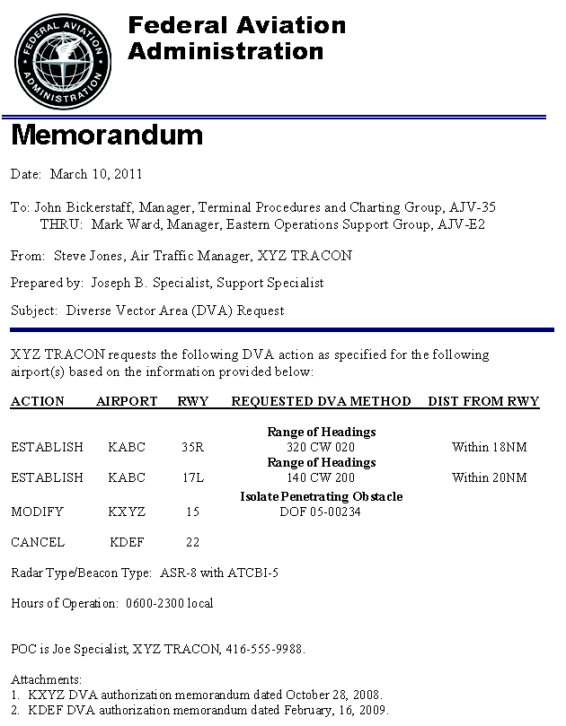
- Forward DVA requests to the Instrument Flight Procedures Group through the appropriate Service Center OSG Manager.
- When a DVA is established, it will be documented and provided to the facility by the Instrument Flight Procedures Group on FAA Form 8260-15D, Diverse Vector Area (DVA). The ATM must then prepare a facility directive describing procedures for vectoring IFR departures below the MVA/MIA including:
- Textual or graphical description of the limits of each airport's DVA for each runway end.
- Where required, specific radar routes, depicted on the radar display, where vectors are provided to aircraft below the MVA/MIA.
- Not utilizing a DVA when a SID or ODP has been assigned or when following missed approaches or go-around instructions.
- IFR aircraft climbing within a DVA must not be assigned an altitude restriction below the MVA/MIA, and must reach the MVA/MIA before leaving the confines of the DVA.
- Headings must not be assigned beyond those authorized by the DVA prior to reaching the MVA/MIA.
- Ensure all controllers are familiar with the provisions of the facility directive before vectoring aircraft in accordance with DVA procedures.