The Runway Safety flashcards were developed to help pilots better understand runway signage and markings. Each card displays an airport sign or pavement marking, while the back of the card provides a description and information on the required pilot action. Flip through the cards and then test your knowledge with a quiz.
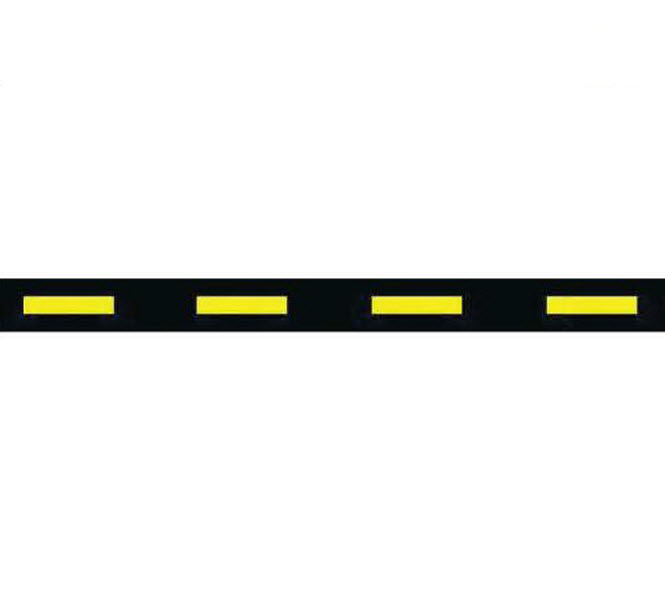
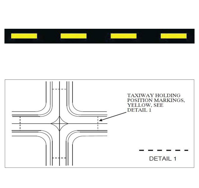
Intermediate Holding Position Marking for Taxiway/Taxiway Intersections
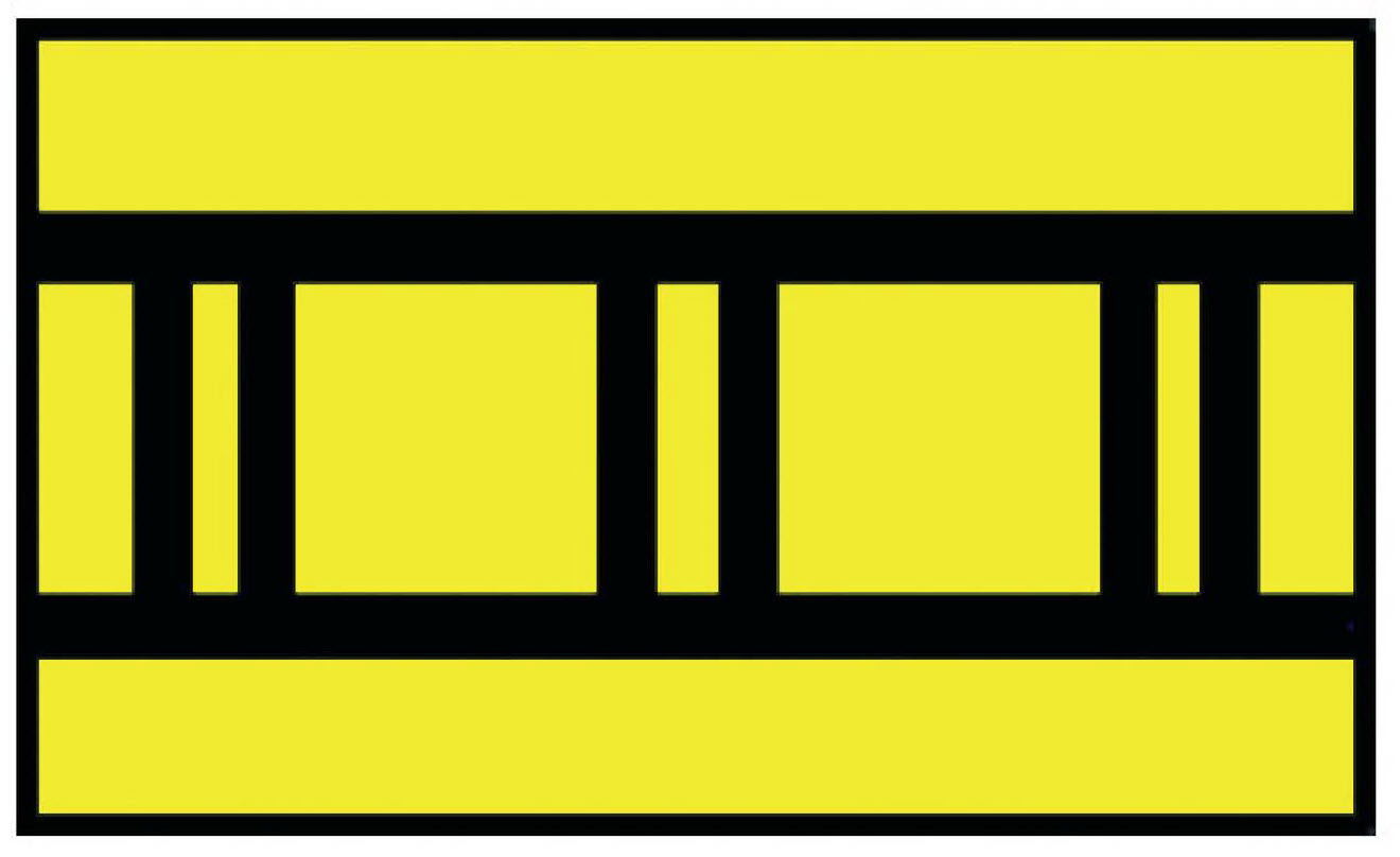
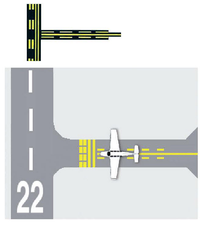
These markings are used to support the operational need by the Air Traffic Control to manage taxiing aircraft through a congested intersection or for other reasons deemed necessary by FAA. Pilots when instructed by the airport traffic control tower to “hold short of (taxiway designation)” must stop so no part of the aircraft extends beyond the boundary of the intermediate holding position marking.
Reference: AIM ¶ 2-3-5
Sample Diagram
Displaced Threshold
Indicates the beginning of the available landing runway. The area before the displaced threshold is available for takeoffs (in either direction) and landings (from the opposite direction).
Reference: AIM ¶ 2-3-3
Sample Diagram
Chevron Markings for Blast Pads, Stopways, and Engineered Materials Arresting Systems (EMAS)
These markings are used to show pavement areas aligned with the runway that are unusable for landing, takeoff, and taxiing. Chevrons are yellow. Chevrons cover blast pads or stopways, which are constructed to protect areas from erosion caused by jet blasts (blast pad) and to provide extra stopping distance for aircraft (stopways).
Reference: AIM ¶ 2-3-3
Sample Diagram
![]()
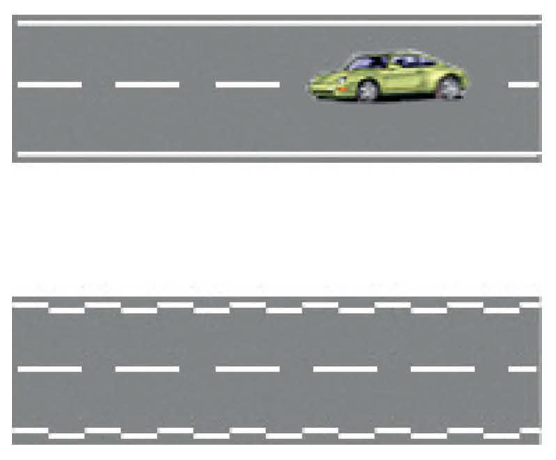
Vehicle Roadway Markings
The vehicle roadway markings are used when necessary to define a pathway for vehicle (non-aircraft) operations on or crossing areas that are also intended for aircraft. These markings consist of a white solid line to delineate each edge of the roadway and a dashed line to separate lanes within the edges of the roadway. In lieu of the solid lines, zipper markings may be used to delineate the edges of the vehicle roadway.
Reference: AIM ¶ 2-3-6
Sample Diagram
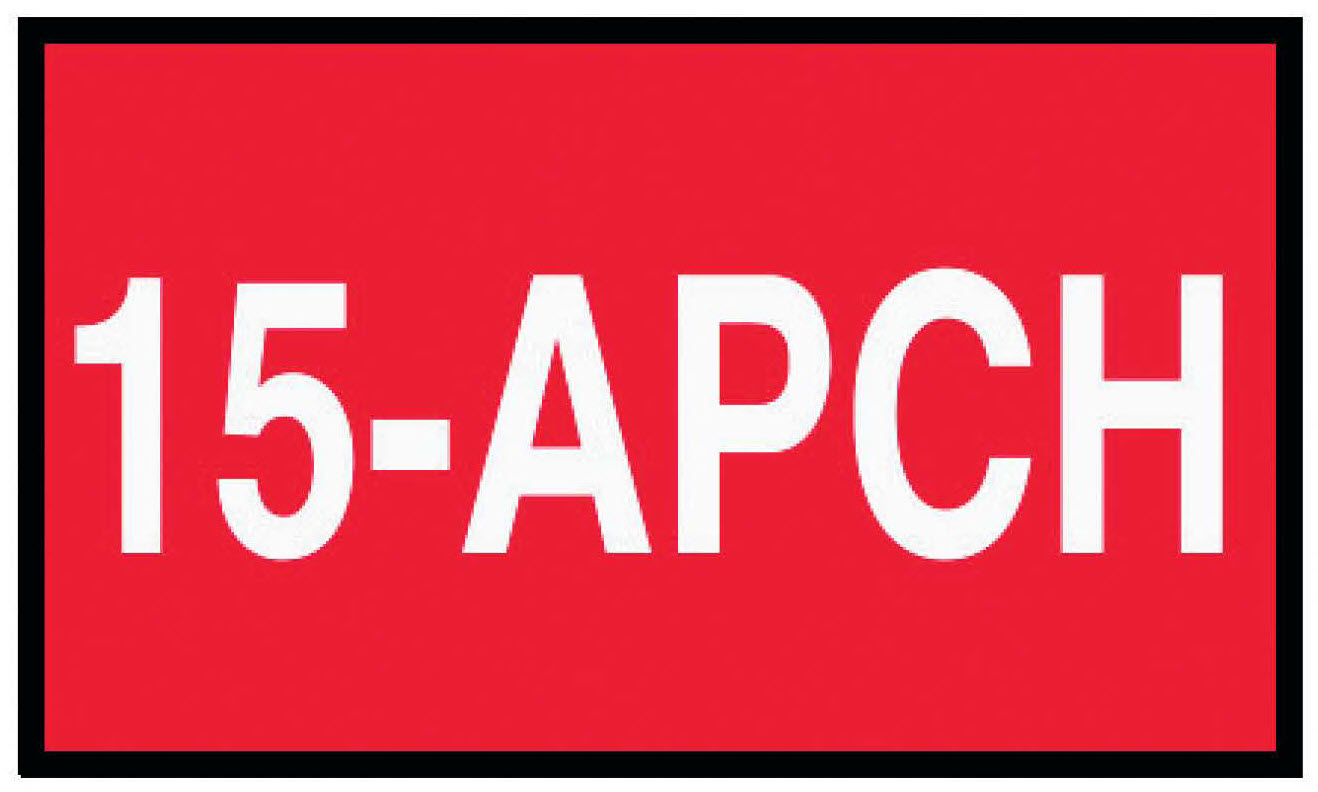
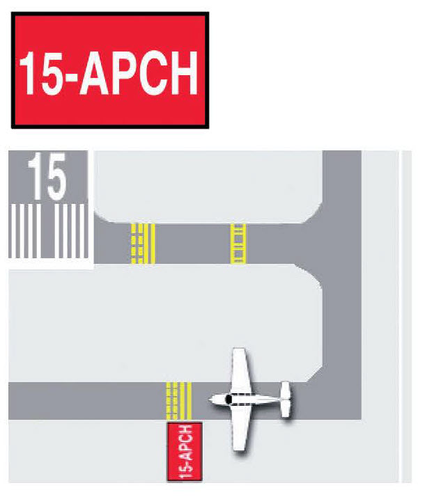
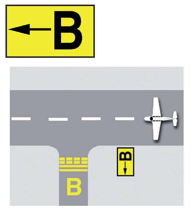
Runway Approach Area Holding Position Sign
Pilots and Vehicle operators must stop short of the Runway Approach Area Holding Position Sign, keeping all parts of the vehicle or aircraft clear of the area when instructed by Air Traffic Control (ATC).
Reference: AIM ¶ 2-3-8
Sample Diagram
ILS Critical Area Boundary Sign
Located next to the Instrument Landing System (ILS) Holding Position Marking. Proceeding past this sign ensures the aircraft or vehicle is clear of the ILS critical area.
Reference: AIM ¶ 2-3-9 and FAA Order 7110.65
Sample Diagram
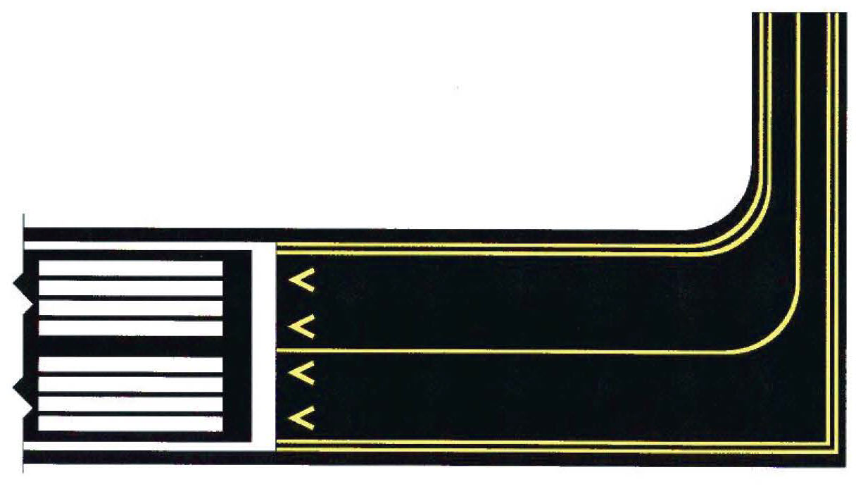
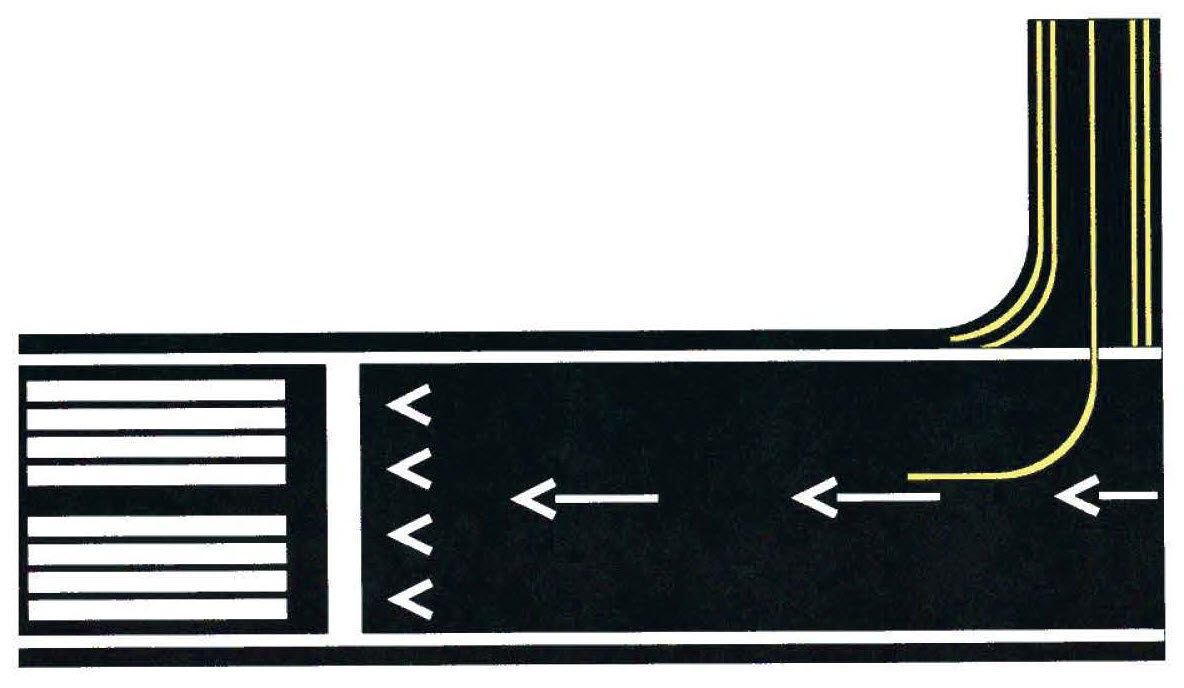
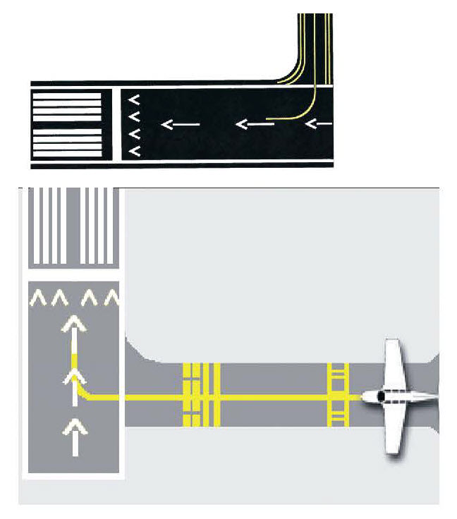
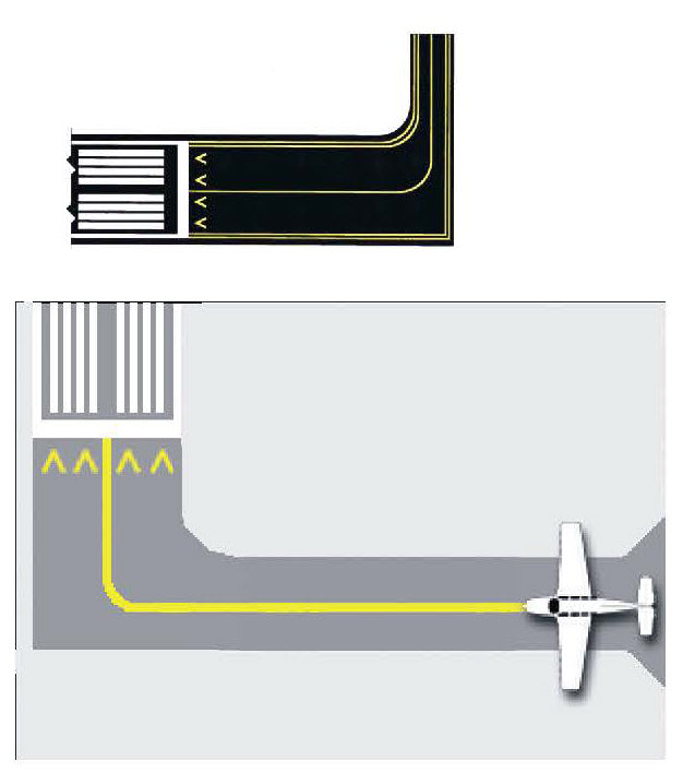
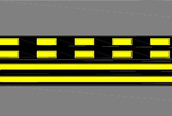
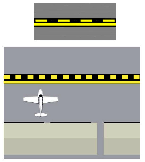
Relocation of a Threshold
Yellow line and arrowhead surface markings indicate that the runway threshold has been closed for take-off and landing operations and that the runway threshold has been moved. The area (with the yellow taxiway centerline and arrow heads) prior to the threshold is usable for (aircraft) taxi only. Possible causes of the threshold relocation include construction or other airport maintenance.
Reference: AIM ¶ 2-3-3
Sample Diagram
Taxiway Location Sign
Indicates the taxiway on which the aircraft is located. (May be co-located with direction signs or runway holding position signs, as shown in graphic.)
Reference: AIM ¶ 2-3-9
Sample Diagram

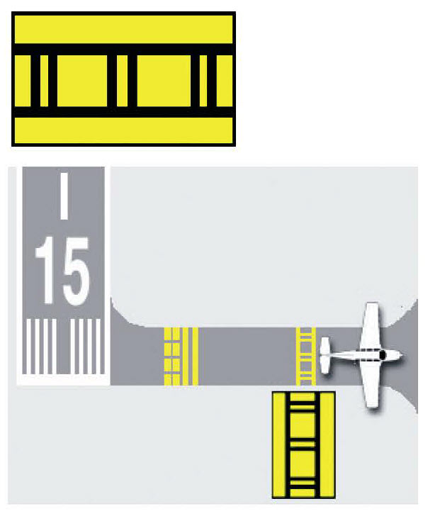
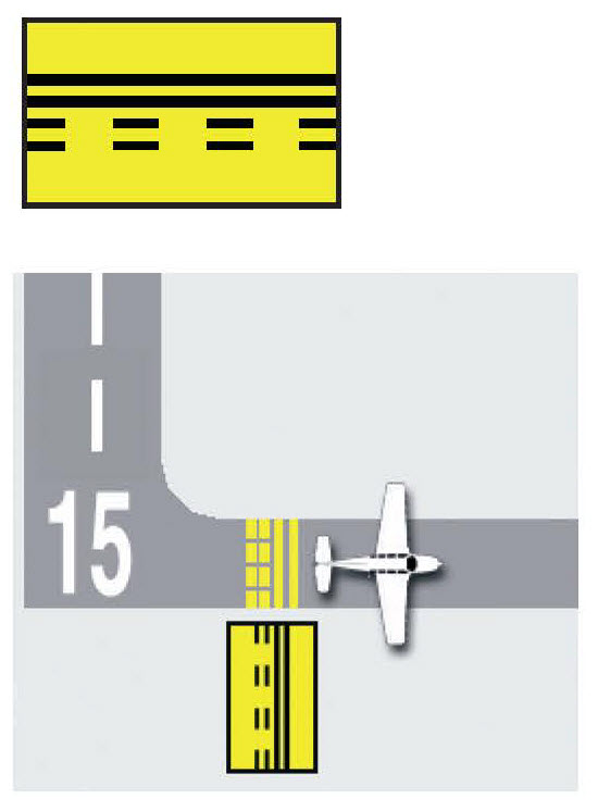
ILS Holding Position Marking
Pilots and vehicle operators must stop short of the ILS Critical Area Holding Position Marking, keeping all parts of the vehicle and or aircraft clear of the area when instructed by Air Traffic Control (ATC). Aircraft and vehicles proceeding past this point may interfere with the ILS signal to approaching aircraft.
Reference: AIM ¶ 2-3-5 and FAA Order 7110.65
Sample Diagram
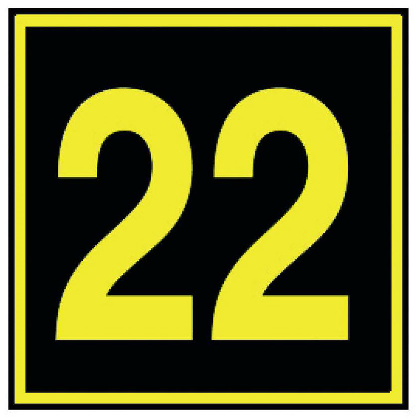
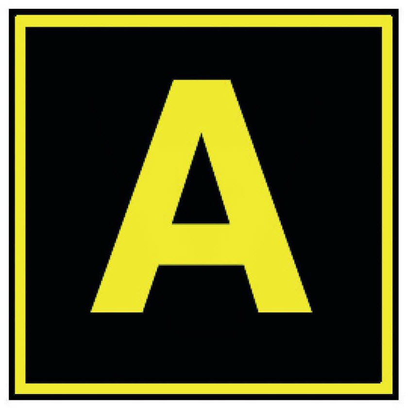
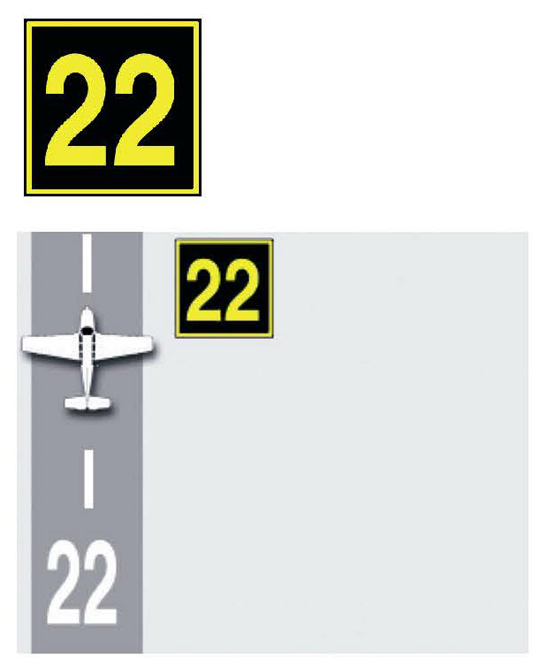
Runway Location Sign
Identifies the runway on which the aircraft is located.
Reference: AIM ¶ 2-3-9
Sample Diagram
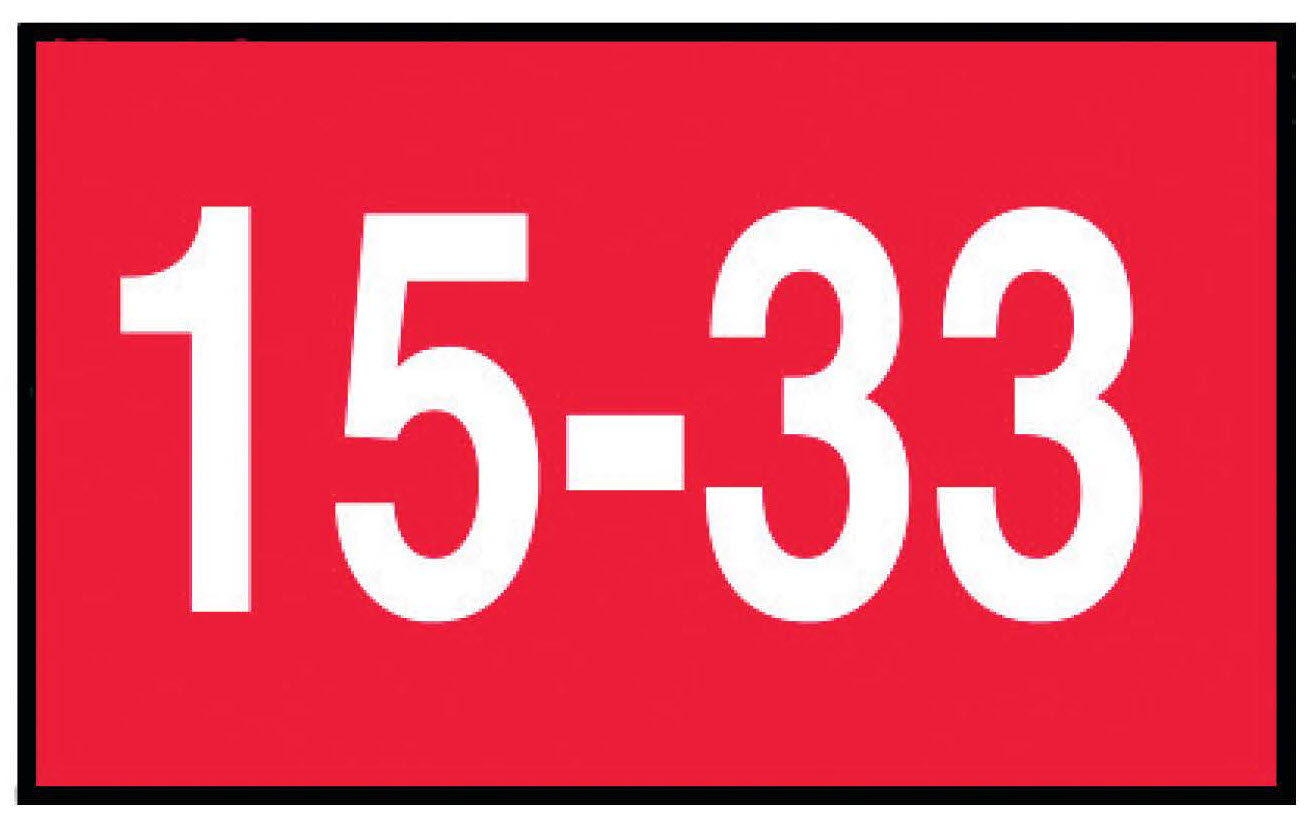
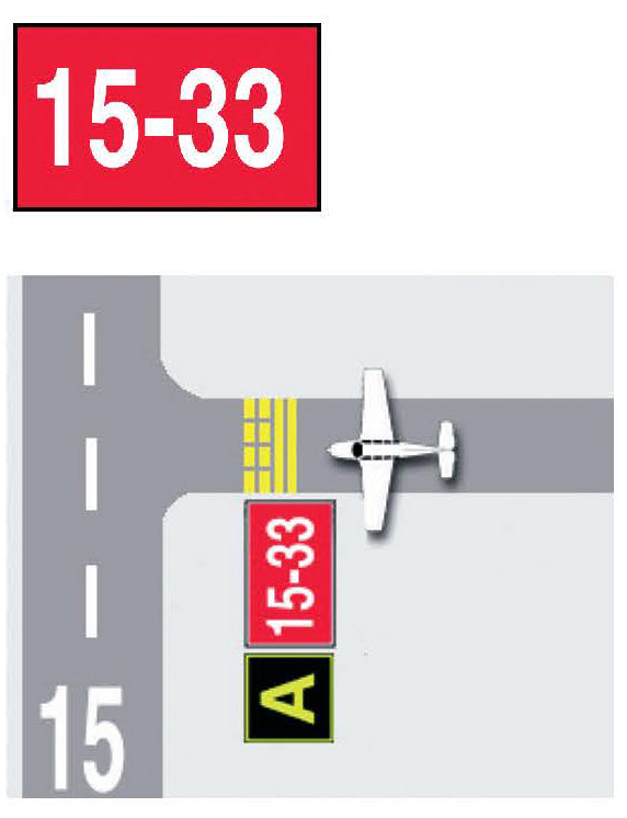
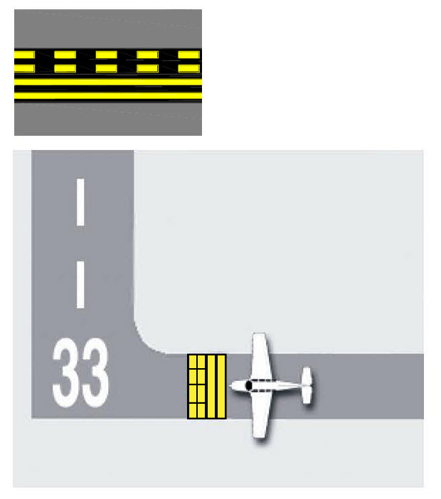
Runway Holding Position Sign
Located next to the Runway Holding Position Markings on taxiways or runway intersections. In this example, the threshold for runway 15 is to the left and the threshold for runway 33 is to the right. Aircraft should not proceed beyond this sign until cleared by Air Traffic Control (ATC).
Reference: AIM ¶ 2-3-8
Sample Diagram
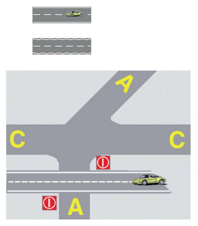
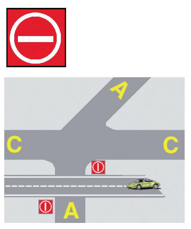
No Entry Sign
Indicates an area where aircraft are not allowed entry. Typically, this sign would be located on a taxiway intended to be used in only one direction or at the intersection of vehicle roadways with runways, taxiways or aprons where the roadway may be mistaken as a taxiway or other aircraft movement surface.
Reference: AIM ¶ 2-3-8
Sample Diagram

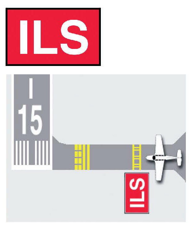
ILS Critical Area Holding Position Sign
Pilots and Vehicle operators must stop short of the ILS Critical Area Holding Position Sign, keeping all parts of the vehicle or aircraft clear of the area when instructed by Air Traffic Control (ATC). Aircraft and vehicles proceeding past this point may interfere with the ILS signal to approaching aircraft.
Reference: AIM ¶ 2-3-8 and FAA Order 7110.65
Sample Diagram
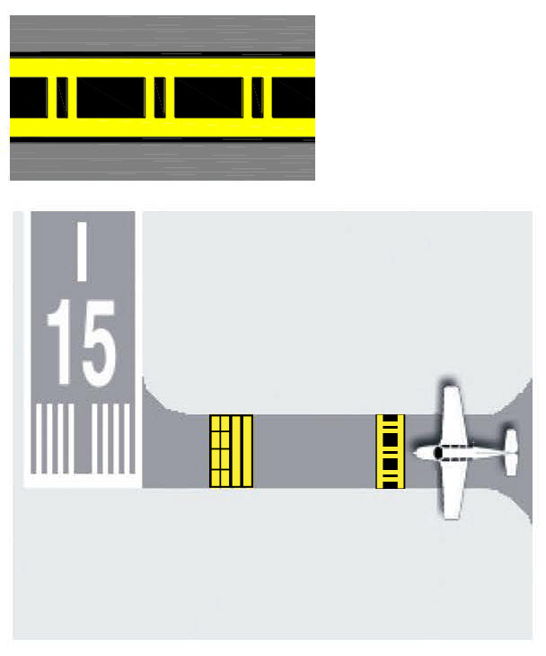
Enhanced Taxiway Centerline Markings
The purpose of this enhancement is to warn the pilot that they are approaching a runway holding position marking and should prepare to stop unless they have been cleared onto or across the runway by Air Traffic Control. The taxiway centerlines are enhanced for a maximum of 150 feet prior to a runway holding position marking.
Reference: AIM ¶ 2-3-4
Sample Diagram
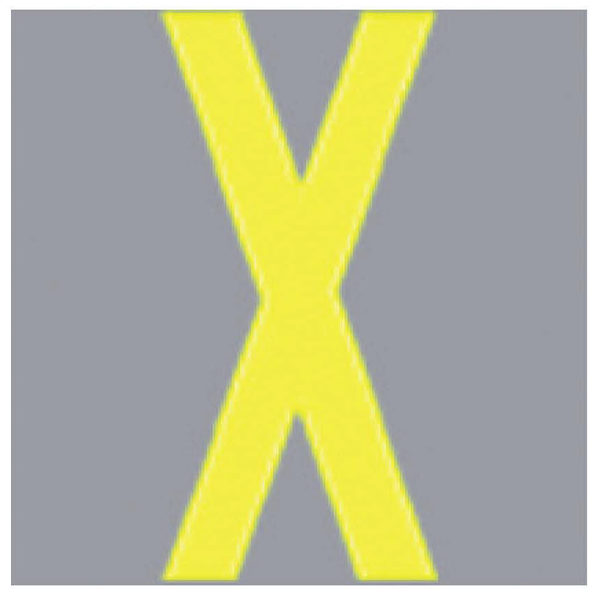
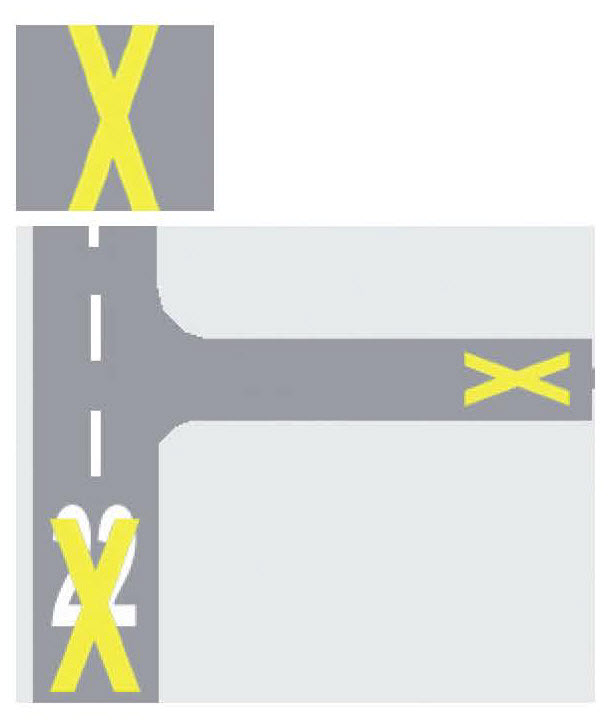
Closed Runway and Taxiway Marking
Indicates a closed runway or taxiway. It will also be placed at each entrance of a permanently closed taxiway. A raised-lighted X may be used in lieu of a pavement marking.
Reference: AC 150/5340-1
Sample Diagram
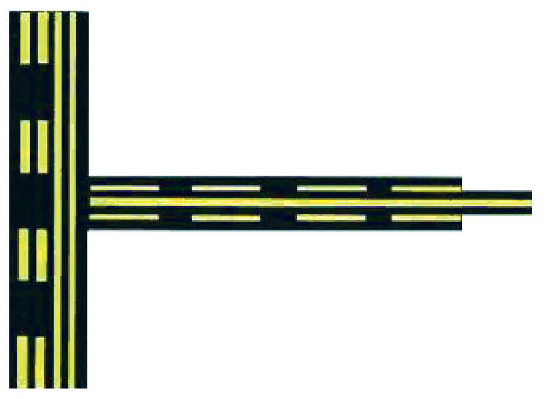
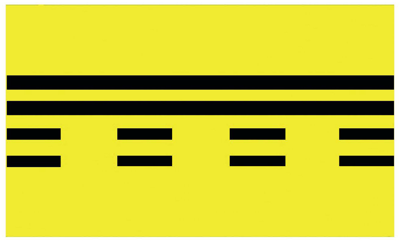
Runway Holding Position Markings
These markings identify the locations on a taxiway where an aircraft or vehicle is supposed to stop when it does not have clearance to proceed onto or cross the runway. These markings are installed on runways only if the runway is normally used by Air Traffic Control for “land and, hold short” operations or taxiing operations and have operational significance only for those two types of operations. The solid lines are on the side where the aircraft is to hold and the dashed lines are on the side toward the runway.
Reference: AIM ¶ 2-3-5
Sample Diagram

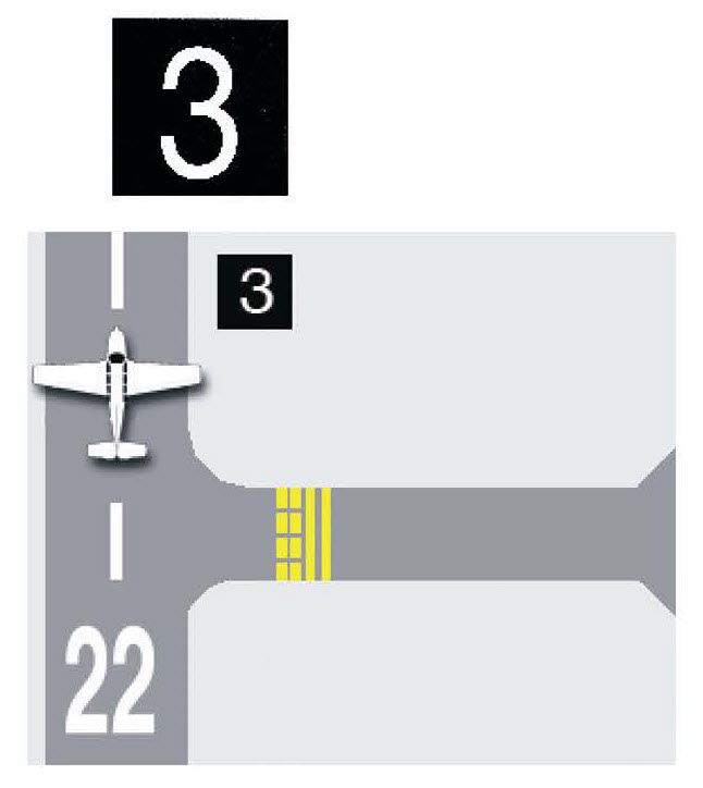
Runway Distance Remaining Sign
Indicates the distance of runway remaining in thousands of feet. In this example, 3,000 feet remain on the landing runway.
Reference: AIM ¶ 2-3-13
Sample Diagram

Taxiway Ending Marker
A taxiway ending marker sign indicates that a taxiway does not continue beyond an intersection normally located on the far side of an intersection if the normal visual cues, such as marking and lighting are inadequate.
Reference: AC 150/5340-18
Sample Diagram
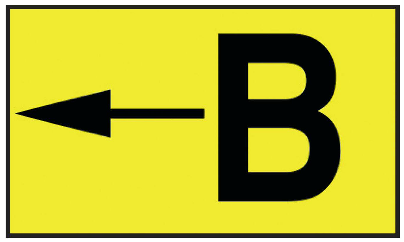
Taxiway Direction Sign
These signs indicate directions and designations of intersecting taxiways.
Reference: AIM ¶ 2-3-10
Sample Diagram
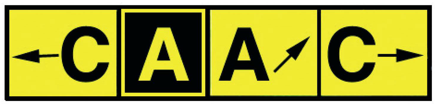
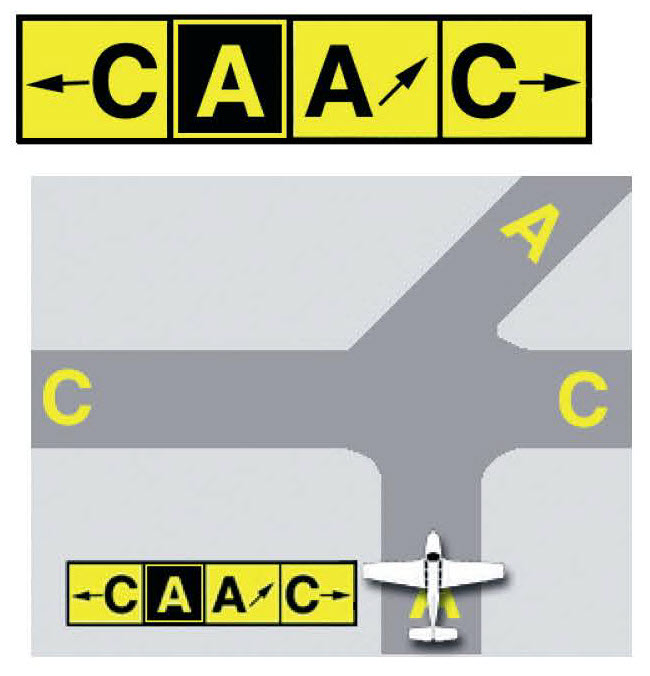
Taxiway Direction Sign
Usually located next to a taxiway location sign, these yellow signs indicate the direction of intersecting taxiways. In this example, taxiway Charlie is to the left and right, and Alpha, which is the taxiway the aircraft or vehicle is currently located on, continues ahead and to the right.
Reference: AIM ¶ 2-3-9 and 2-3-10
Sample Diagram
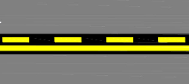
Non-Movement Area Boundary Markings
The non-movement area boundary marking is used to delineate the movement areas, which are under Air Traffic Control, from the non-movement areas. The solid side of the line is on the non-movement area side and the dashed side is on the movement area side.
Reference: AC 150/5340-1
Sample Diagram
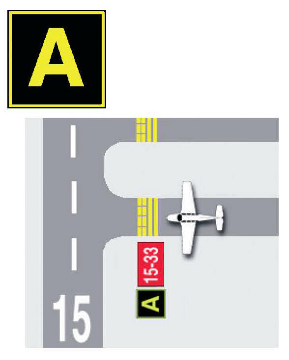
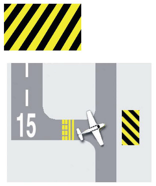
Runway Boundary Sign
This sign faces the runway and is visible to pilots and vehicle operators exiting the runway. It is located next to the yellow Runway Holding Position Marking painted on the taxiway pavement. Proceed past this sign to be clear of the runway.
Reference: AIM ¶ 2-3-9
Sample Diagram
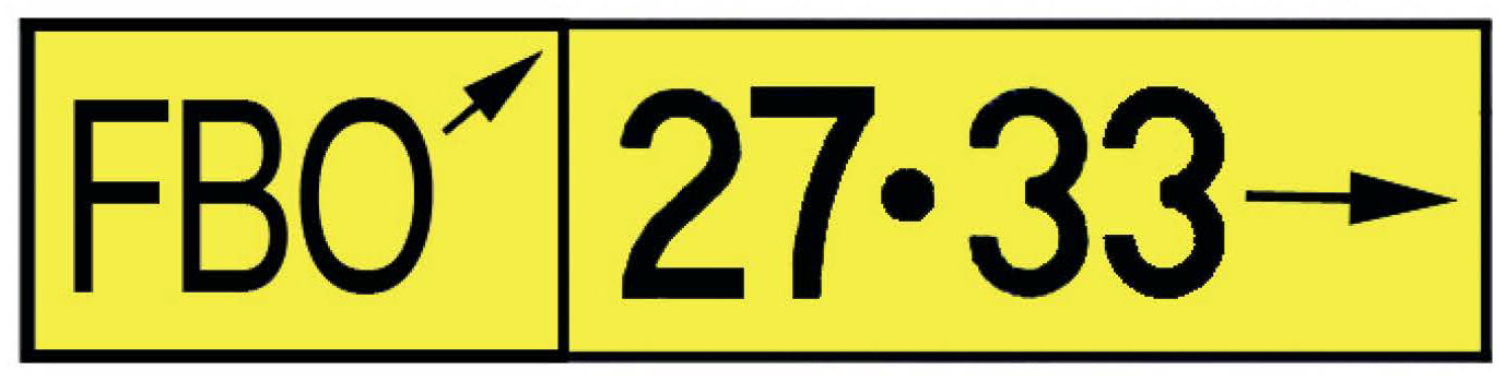
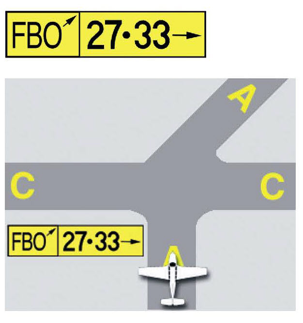
Destination Sign
Indicates the direction of a taxi route to a runway(s) or other location. In this example, the fixed base operator (FBO) is ahead and to the right, and runways 27 and 33 are to the immediate right.
Reference: AIM ¶ 2-3-11
Sample Diagram