
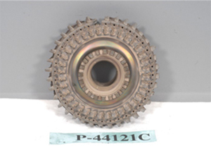
Fairchild SA227
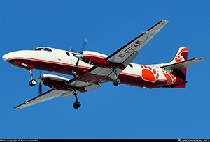
Photo copyright Pierre Lacombe – used with permission
Bearskin Flight 311, C-FFZN
Red Lake, Ontario
November 10, 2013
On November 10, 2013, Bearskin Flight 311 from Sioux Lookout, Ontario crashed on approach to the Red Lake Ontario Airport. Both pilots and three passengers were fatally injured, and two passengers survived. While on final approach to the airport and about 500 feet above the ground, the crew noted an aircraft malfunction, but did not describe the condition to Air Traffic Control (ATC). Shortly thereafter the crew declared an emergency. The airplane then veered and rolled to the left, descended, and impacted trees and electric power lines before coming to rest adjacent to Ontario Highway 125. The airplane was destroyed by impact and post-crash fire.
Investigators determined that the left engine turbine wheel blade failed and led to the left propeller being at a high RPM. With the airplane in the landing configuration, the left propeller created a high drag state and the airplane rolled to the left in an asymmetric condition. The airplane’s speed slowed below minimum control speed (Vmcl) for the airplane's configuration.
The Transportation Safety Board of Canada determined that the left engine experienced a near total loss of power as the aircraft was on final approach to the Red Lake Airport. The crew failed to take the necessary actions needed to maintain control of the airplane, which would have included manually feathering the left propeller.
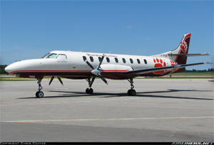
Photo copyright Chris Coates - used with permission
History of the Flight
Bearskin Lake Air Service LP Flight 311 (Bearskin 311) was a scheduled flight between Thunder Bay, Ontario and Winnipeg, Manitoba with stops in Sioux Lookout and Red Lake, Ontario. As the crew prepared for final approach, they stabilized the airspeed at 140 knots.
As the aircraft descended through 1,780 feet and slowed to approximately 130 knots with torque on both engines at 23% and N1 on both engines at 100%, the left engine suddenly failed. The engine failure was picked up by the cockpit voice recorder (CVR) as a loud tone. The crew appeared to have pushed the power levers forward commanding increased power. The right engine responded with a torque increase from 34% to 108% over the next three seconds while torque on the left engine remained fluctuating between -2% and +7% per the flight data recorder (FDR). The aircraft was in an asymmetric thrust condition (yawing and rolling).
The TPE331 engine is designed to activate a negative torque sensing (NTS) system to increase blade angle if it senses a negative engine torque from -3% to -4%. The left engine NTS system was likely not operating because the engine had not completely lost power and was developing torque greater than the -4% value required to activate it.
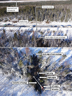
Transportation Safety Board of Canada report photo
View Larger
The airplane's landing configuration generated higher drag which, combined with the power loss, caused a reduction in airspeed. When the airspeed decreased to 116 knots, the crew told ATC they had a malfunction but did not elaborate. With the increased torque on the right engine, the aircraft yawed and rolled left and accelerated to 124 knots. The crew retracted the landing gear, but then reselected the gear down before it could fully retract. The pilots reduced torque on the right engine to 91% and then again to 54% with the airspeed showing to 101 knots. Investigators presumed this was to initiate a descent to the runway.
In response to a pilot monitoring instruction to climb, the pilot increased the right engine power to 98% which exacerbated the aircraft's asymmetry and the aircraft rolled left to 41° of bank when the airspeed reached 98 knots. The bank angle continued to increase as the aircraft descended and impacted terrain 52 seconds after the left engine failure.
The aircraft first made contact with terrain when it struck trees while in a steep left-wing, low attitude approximately 2,300 feet south of the approach end of Runway 26. On initial contact an eight-foot section of the outboard left wing was torn off, and the aircraft travelled approximately 375 feet before striking electrical power lines running along Ontario Highway 125 that led to the airport. The aircraft contacted the south embankment of the highway. Upon impact with the embankment, the left engine and propeller separated from the aircraft. The aircraft cartwheeled and slid tail first to a point 150 feet from the highway in an area of trees. The right wing and engine separated from the aircraft, and the left engine was located underneath the tail section. Left and right propellers detached from their engines. The fuselage forward of the wing was severely crushed and deformed, while aft of the wing the fuselage remained mostly intact.
There are several technical and operational issues that are important to this accident, including:
- TPE331 engine control
- Turbo-propeller fundamentals (feathering)
- NTS system
- Engine failure procedures
- Engine fatigue failure
- Vmcg vs. Vmcl
TPE331 Engine Control
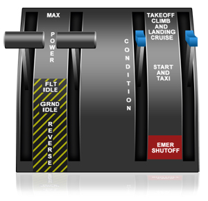
The Fairchild SA-227-AC Metro III has a Honeywell TPE331 engine. The engine power gauges display engine torque and turbine N1 (turbine shaft) RPM. The pilot selects the desired RPM range for each engine using the condition levers (blue in the picture) and controls the torque output with the power levers (black in the picture).
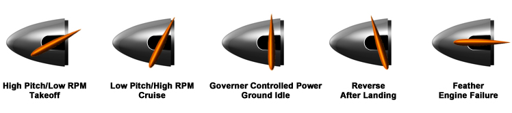
The taxi position controls RPM at approximately 74% on the ground. For takeoff and landing, the propeller governor regulates engine turbine RPM to 100%. For normal cruise, the pilot selects RPM between 96% and 97%. Pulling the condition lever full aft shuts the engine down and feathers the propeller.
The power lever operational range is divided into two regions: flight region and ground-operating region. In the FLIGHT RANGE, the power lever regulates the fuel flow to the engine and the propeller governor controls the propeller pitch. A condition lever maintains propeller RPM at an angle that results in a given torque. In the GROUND RANGE, the power lever directly controls the propeller pitch and the propeller governor maintains selected engine RPM. The ground operating region, when the power levers are between flight idle and maximum reverse thrust, is known as the BETA RANGE.
Turbo-propeller Fundamentals (Feathering)
In the event of an engine failure, a rotating propeller produces significant drag. In a multi-engine aircraft, feathering the propellers turns the blades to be aligned with airflow, stopping rotation and creating minimal drag. In cruise, the propeller is at a low blade angle (high RPM). With a power loss, this produces significant drag to the point the aircraft may become uncontrollable. Depending upon single-engine performance, feathering often permits continued flight to the nearest airport following an engine failure.
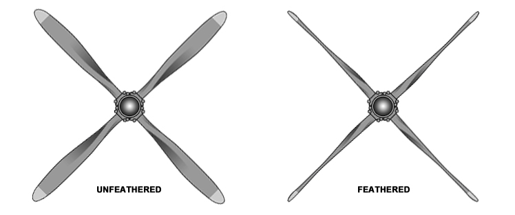
The aircraft is equipped with two McCauley four-bladed, constant-speed, aluminum propellers. Springs and counterweights move the blades towards low RPM (high pitch) and the propeller governor oil moves the blades to high RPM (low pitch).
View Larger
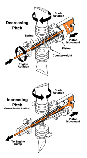
The propeller uses a governor to hydraulically control blade angle position. A cylinder is attached to the propeller hub and contains a feathering spring and a hydraulically actuated piston. The piston is attached to a pitch change mechanism that adjusts the blade angles.
When the airplane engine cockpit controls are positioned for taxi, takeoff, or flight, oil flows into the propeller piston, allowing the propeller blade angle to be controlled by the governor. When the crew commands the propeller to feather, oil flows out of the piston, allowing the feathering spring to force the blades towards a feather position.
Full feather is about 89 degrees blade angle. The crew feathers the propeller by activating the engine stop-and-feather control in the cockpit. This cuts fuel to the engine (stopping engine rotation) and allows the propeller governor to vent oil to the engine sump, thus increasing the blade angle towards feather. When oil leaves the piston, the feathering spring and counterweights can move the propeller blades into the feathered position.
NTS System
Airplanes powered by Honeywell TPE331 engines do not have an automatic full-feathering system, but rather a negative torque sensing (NTS) system.
The purpose of the NTS is to reduce propeller drag forces that cause excessive yaw on the aircraft if an engine fails. The NTS senses negative torque when a windmilling propeller drives the engine. When a negative torque is sensed, oil in the propeller is used to control blade angle, allowing the propeller blades to move towards a higher pitch (lower RPM) position. The NTS reacts at a low enough negative torque value to prevent excessive inflight drag, while also maintaining sufficient engine RPM to accomplish a windmilling engine restart. To accomplish this, the NTS is designed to activate upon sensing a negative torque of -3% to -4%.
Positive torque is when the engine is driving the propeller. Negative torque is produced when the windmilling propeller is driving the engine. A torque sensor detects both positive and negative engine torque. When the torque sensor detects negative torque, oil from the prop governor system moves a pilot valve to a position that allows the propeller control oil to vent. The propeller feathering spring and counterweights momentarily move the propeller blades towards a higher blade angle, thus reducing negative torque.
If negative torque becomes sufficiently reduced, the pilot valve moves back towards its original position, returning control pressure to the propeller and driving the propeller to a lower blade angle (higher RPM). As the propeller moves to a lower blade angle, the torque sensor may again sense a negative torque and repeats the cycle. The cycling of the propeller blades from high to lower blade angles by the NTS is termed "NTS-ing."
The NTS does not feather the propeller; however, it increases blade angle enough to provide partial anti-drag protection. In this accident it did not activate due to the massive engine failure; however, per specifications, the system would have activated at -3% to -4%.
A properly operating NTS should reduce propeller drag sufficiently for the pilot to maintain safe control of the airplane. The NTS is designed to allow the pilot time to determine which engine has a problem and make a decision whether to restart the engine or fully feather the propeller and continue the flight on a single engine.
Engine Failure Procedures
The SA227-AC Airplane Flight Manual (AFM) was revised to add the following warning information that a pilot's sole reliance on the NTS for reducing drag in the event of engine power loss may result in the pilot's failure to initiate the Engine Failure Inflight checklist and therefore fail to feather the propeller in time. This failure could lead the pilot to not manually feather the propeller, resulting in airplane loss of control.
WARNING:
IN THE EVENT OF AN ENGINE FAILURE OR POWER LOSS, THE ENGINE NEGATIVE TORQUE SYSTEM (NTS) ONLY PROVIDES PARTIAL DRAG REDUCTION BUT NOT TO THE EXTENT OF A FULLY FEATHERED PROPELLER.
PILOT MUST TAKE ACTION TO FULLY FEATHER THE PROPELLER (ON THE AFFECTED ENGINE) TO REDUCE PROPELLER DRAG.
View: SA227-AC Flight Manual Engine Failure Procedures with changes indicated with side bar
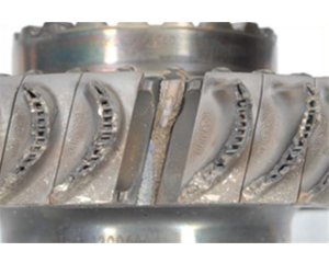
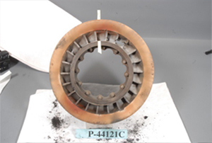
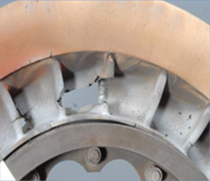
Engine Fatigue Failure
View Larger
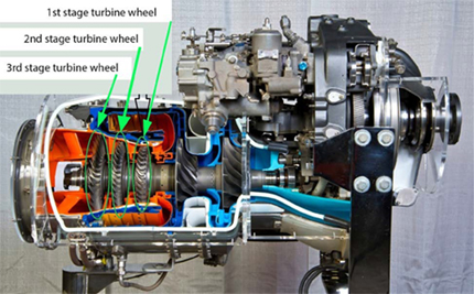
Investigators disassembled the failed engine turbine section. The first-stage wheel was found to be stripped of all blades down to the blade roots with one blade failing at the blade root area. The area of failure exhibited a distinct fatigue zone near the trailing edge of the blade and was sent to the laboratory for metallurgical examination. The examination concluded that the blade failure occurred as a result of high-cycle fatigue in an area of high porosity.
The first-stage stator (nozzle) assembly was examined and burn-through was noted on one of the stationary nozzle vanes. Several other nozzle vanes showed areas of cracking, material loss, and heat distress. The stationary first-stage stator assembly is upstream of the first-stage turbine wheel and directs hot combustion air onto the rotating turbine wheel.
The engine manufacturer indicated that there had been previous incidents of two types of failure: first-stage turbine wheel blade failure and stator burn-through. There have been cases where both failures occurred in conjunction with one another and at other times only the turbine wheel blade failed. The turbine wheel blade failures have been attributed in some instances to porosity issues in the casting process and/or fatigue issues caused by excessive turbine distress due to stator vane burn-through. A burn-through in the stator vane produces a vibrational response (one per revolution) in the blades that can lead to the blades separating in a high-cycle fatigue mode. Stator vane burn-through has been attributed to streaking fuel nozzles or the blockage of the first-stage stator cooling tubes which could cause hot spots on the stator vane.
As part of the investigation, the engine manufacturer conducted a root and contributing cause analysis of the turbine blade separation. The analysis focused on the fatigue life capability, mean stress/loading, alternating stress/loading, mechanical vibratory characteristics, and material characteristics.
In summary, the manufacturer's contributing cause analysis determined that the first-stage turbine wheel failed because of high-cycle fatigue which was the result of the following factors:
- Substandard porosity of the turbine blade material which resulted in inadequate fatigue capability and the creation a favorable location for cracking initiation.
- A minor increase in the mean stress in the blade root area due to blade platform contact.
- Stator burn-through, which resulted in an uneven vibration on the front-stage turbine wheel assembly and heat stress on the turbine blades.
The examination of the engine concluded that, in this occurrence, the failure of the first-stage turbine blade by itself would not have caused the engine to lose all power. However, its failure caused damage to the remaining turbine blades, which reduced the efficiency of the engine and would have greatly reduced the power output of the engine to drive the propeller (negative torque).
The investigation revealed discrepancies between the manufacturer's maintenance and fuel nozzle overhaul manuals. Consequently, examining fuel nozzles as per the maintenance manual might result in a nozzle being deemed unserviceable, whereas testing as per the overhaul manual might result in the same nozzle being evaluated as serviceable. The number 9 fuel nozzle in the occurrence aircraft's left engine had at one time been removed, tested, and found unserviceable. It was then sent out for overhaul, tested according to the instructions in the fuel nozzle overhaul manual, found serviceable, and then reinstalled in the left engine.
Vmcg vs. Vmcl
Vmcg (velocity minimum control ground) is the minimum speed on the ground that directional control can be maintained using only aerodynamic controls (e.g. rudder) with the critical engine inoperative and takeoff power applied on the other engine. It is published in the AFM.
At the time the Model SA227-AC was certificated to 14 CFR part 23 amendment 23-6 in 1981, §23.149 required Vmcg be shown only in the takeoff configuration. Vmcg for the accident aircraft had been established at 91 knots, and the cockpit airspeed indicator was marked with a red line at this airspeed.
Vmcl (velocity minimum control landing) is the minimum control speed during landing approach with all engines operating, is the calibrated airspeed at which, when the critical engine is suddenly made inoperative, it is possible to maintain control of the airplane with that engine still inoperative and maintain straight flight with an angle of bank of not more than 5º. Establishment of Vmcl in the landing configuration was not required by regulation until amendment 23-50 was incorporated in 14 CFR part 23 in February 1996. Investigators could find no evidence that Vmcl had been determined for the Model SA227-AC.
After the accident, flight tests were performed to help gain a better understanding of Vmcl for the accident airplane. Results of flight test showed that Vmcl should be at least 105 knots; 14 knots above the published Vmcg and could be higher depending on configuration settings.
Conclusion
Several technical and operational issues were important to this accident. From the FDR data, investigators found the crew could not maintain control of the airplane since they were near stall speed and below the landing configuration Vmcl.
Engine fatigue failure, crew misunderstanding of the NTS, and crew failure to immediately feather the propeller were primary causal factors. Contributing factors were the Airplane Flight Manual (AFM) manual and Pilot Operating Handbook (POH), which led the crew to believe the NTS would reduce significant drag during engine failure and provide more protection that it was designed. As a result, TSB recommended the manuals be updated to clearly convey that the NTS is not designed to automatically feather the propeller but only provides limited drag protection. The FAA issued an Airworthiness Directive in April 2016 that required these manual updates.
The Transportation Safety Board of Canada determined that as a result of a turbine wheel blade failure in the left engine, the affected engine experienced a near total loss of power as the aircraft was on final approach to the Red Lake Airport. Investigators determined that the crew did not take prompt action to feather the propeller on the failed engine, which resulted in loss of control.
The following are additional causes and contributing factors that can be found in section 3.0 of the Accident Report:
- A first-stage turbine wheel blade in the left engine failed due to a combination of metallurgical issues and stator vane burn-through.
- As a result of the blade failure, the left engine continued to operate but experienced a near-total loss of power at approximately 500 feet above ground level, on final approach to Runway 26 at the Red Lake Airport.
- The crew were unable to identify the nature of the engine malfunction, which prevented them from taking timely and appropriate action to control the aircraft.
- The nature of the engine malfunction resulted in the left propeller being at a very low blade angle, which, together with the landing configuration of the aircraft, resulted in the aircraft being in an increasingly high drag and asymmetric state. When the aircraft's speed reduced below minimum control speed (Vmc), the crew lost control at an altitude from which a recovery was not possible.
The complete text of findings as to risk and other findings is available at the following link Accident Report.
According to the accident report, "The Safety Advisory suggested that Transport Canada may wish to advise operators of these aircraft to review the NTS systems description in their training manuals and standard operating procedures (SOPs) for engine failures. The advisory further stated that particular attention should be directed to flight crews operating these aircraft types to initiate SOPs in a timely manner when an engine failure occurs."
The complete text of the recommendation and related information can be read in the Transportation Safety Board of Canada accident report, section 4.1.1 through section 4.1.4 from the following link: Accident Report
14 CFR 23.149 Minimum Control Speed
The Model SA227-AC certification basis included §23.149 Amendment 6, Minimum control speed. A determination of Vmc in the landing configuration (Vmcl) was not required for aircraft certificated at this amendment. A Notice of Proposed Rulemaking (NPRM) was issued in 1994 and a final rule was published in 1996 to amend Sec. 23.149 to add a Vmc for the landing configuration. The rule established compliance with Amendment 50 for airplanes with a certification basis effective 1996. Amendment 50 defined a critical engine and added Vmcl requirements for airplanes of greater than 6,000 pounds.
14 CFR 23.149 Minimum control speed Amendment 6
14 CFR 23.149 Minimum control speed Amendment 50
14 CFR 23.903(c) (1 and 2) Engines
For small airplanes:
"(c) The powerplants must be arranged and isolated from each other to allow operation, in at least one configuration, so that the failure or malfunction of any engine, or the failure or malfunction (including destruction by fire in the engine compartment) of any system that can affect an engine (other than a fuel tank if only one fuel tank is installed), will not:
(1) Prevent the continued safe operation of the remaining engines; or
(2) Require immediate action by any crewmember for continued safe operation of the remaining engines."
This means the pilot may manually activate the feathering system, or the system may automatically activate auto-feather following failure of the first engine.
However, for large transport aircraft certified under 14 CFR part 25.903(b) (1 and 2) Engine Isolation:
"(b) Engine Isolation. The powerplants must be arranged an isolated from each other to allow operation, in at least one configuration, so that the failure or malfunction of any engine, or of any system that can affect the engine, will not -
(1) Prevent the continued safe operation of the remaining engines; or
(2) Require immediate action by any crewmember for continued safe operation."
It is important to note that the installation of engines on small airplanes may permit the required manual feathering of the propeller following failure of the first engine. In contrast, large airplanes certified under 14 CFR part 25, would prohibit immediate crew action being necessary in order to maintain safe operation of the airplane. As such, auto-feather systems are required to maintain airplane controllability following engine failure.
14 CFR 23.937 Turbo-propeller Drag Limiting Systems
This regulation specifies that turbo-propeller drag-limiting systems (i.e., feathering systems) must be designed so that no single failure or malfunction results in catastrophic structural damage to the airplane.
These three primary regulations, when considered together, allow for the application of manual feathering of the propeller control systems on 14 CFR part 23 small turbo-propeller aircraft in order to decrease drag and maintain aircraft control.
Engine-out procedures
The emergency procedures section of the SA227 Metro III Aircraft Flight Manual (AFM) and amendment 7 of the Bearskin Airlines Metro SOPs provided guidance for handling an engine failure during takeoff or in flight. Crews had no specific guidance in either manual for an engine failure on short final approach. For an engine failure during takeoff or in flight, the course of action was to identify the failed engine and to activate the engine stop-and-propeller feathering system. A caution in both manuals instructed the crew to keep the power lever of the failed engine well forward to command high propeller blade angle (low RPM) and thereby reduce the windmilling propeller drag in the event that an NTS failure accompanied an engine failure.
The Bearskin Airlines SOPs for a non-precision engine-out approach required the crew to re-configure the aircraft three times during the final stages of the approach. Investigators concluded that frequent configuration changes over a short distance or period of time can lead to confusion as to the configuration state of the aircraft.
- Asymmetric drag - Asymmetric drag significantly reduces aircraft performance and is the reason it is important to feather the propeller of the failed engine. In this aircraft, asymmetric drag is eliminated when the propeller is feathered.
- Flightcrew misunderstanding - Flightcrew understanding of the NTS was limited and documentation did not accurately describe the system. Thus, pilots misinterpreted the purpose or function of the NTS in the event of an engine power loss. The SA227-AC AFM was revised to add warning information that a pilot's sole reliance on the NTS for reducing drag in the event of engine power loss may result in failure to feather the propellers in time.
Aircraft manuals provide clear and accurate information and procedures.
- The investigation revealed that the descriptions of the NTS in several SA227/SA226 training manuals were such that pilots could interpret them to mean that the system would automatically provide significant anti-drag protection in the event of an engine failure or power loss. The NTS provides anti-drag protection if negative torque is sensed, but not to the extent provided by a fully feathered propeller.
When one engine of a multi-engine aircraft experiences a loss of power, pilots recognize the engine condition and conduct appropriate emergency procedures.
- The crew noted an aircraft malfunction but applied ineffective procedures in dealing with the asymmetric thrust condition. Investigators concluded that due to crewmember misunderstanding of NTS, they failed to manually feather the propeller and lost control of the airplane.
In 2009, a Fairchild SA227-DC was on final approach when the right engine (Garrett TPE331-11U-612G) suddenly failed. Information provided indicated that the failed engine's propeller NTS system was not functioning after the engine failure and that the aircraft was difficult to control until the right propeller was feathered.
- Transportation Safety Board of Canada issued Safety Advisory 825-A13C0150-D1-A1, Operations of Aircraft with Negative Torque Sensing Systems, April 25, 2015.
- Transport Canada published a Civil Aviation Safety Alert (CASA 2014-04) concerning issues associated with NTS systems installed on TPE-331 series engines. This required operators to amend their manuals, SOPs, and training in accordance with the manufacturers' recommendations of operating procedures that address NTS systems and failures. This communication emphasized the necessity for securing and verifying that propellers are feathered and secured after an engine power loss event.
- Honeywell issued Service Bulletin TPE 331-73-0284 to reduce the fuel nozzle inspection interval from 450 to 350 hours, introduced turbine blade production changes to reduce or eliminate porosity issues in turbine blades, and updated the maintenance manuals to remove discrepancies in fuel nozzle testing procedures.
- Based on reports of similar TPE-331 engine turbine blade failures the FAA published SAIB NE-16-19 recommending specific engine component inspections.
- M7 Aerospace, the successor to Fairchild Aviation, added information to the Airplane Flight Manual (AFM) and/or Pilot's Operating Handbook (POH) that reliance on the NTS to reduce drag during an engine failure could lead the pilot to not fully feather the propeller with consequent loss of control.
- Bearskin Airlines amended its training program to include updated single-engine procedures, engine failure drills on short final, and in-depth discussion of the NTS system in ground school training.
AD 2016-04-04
Unsafe Condition
This AD was prompted by information that a pilot's sole reliance on the negative torque sensing system (NTS) for reducing drag in the event of engine power loss may result in the pilot's failure to initiate the Engine Failure Inflight checklist and feather the propellers in time. This could lead the pilot to not fully feathering the propeller with consequent loss of control. This AD added information to the Airplane Flight Manual (AFM) and/or Pilot's Operating Handbook (POH) that reliance on the NTS system to reduce drag during an engine failure could lead the pilot to not fully feather the propeller with consequent loss of control. AD 2016-04-04
Airplane Life Cycle
- Design / Manufacturing
- Operational
- Maintenance / Repair / Alteration
Accident Threats
- Loss of Control
- Engine / Component Failure
Operations
- Business/Commercial
Accident Common Themes
- Organizational Lapses
- Human Error
- Flawed Assumptions
- Pre-existing Failures
- Unintended Effects
Organizational Lapses
Pilots may not have been properly trained on handling engine failures, in that asymmetric drag causes significant loss of aircraft performance if the propeller has not been feathered.
Human Error
The crew failed to manually feather the propeller.
Flawed Assumptions
Pilots may have assumed that if an engine failed, the NTS would significantly reduce drag on the airplane, and they could delay feathering. Misinterpretation by flight crews of the purpose or function of the NTS may lead them to believe that the NTS always activates in the event of a power loss or that NTS activation alone provides adequate anti-drag protection. As a result, flight crews may not feather the propeller in a timely manner.
Preexisting Failures
The failed engine's first stage turbine blade developed fatigue crack in an area of high porosity. Enhanced inspection procedures may have discovered deteriorating internal engine conditions and turbine blade cracks before an engine failure occurred.
Photo copyright Malcolm Taylor – used with permission
NTSB Identification: ANC09LA009
Aircraft: Construcciones Aeronautics SA CASA 212, registration: N437RA
Accident Occurred: November 1, 2008
Injuries: 2 minor
The first officer turned the airplane from base leg to final and advanced the engine power levers to increase engine power. The right engine did not respond, resulting in the airplane yawing to the right. The captain took over and began a go-around by adding full engine power. As the power increased, the yaw intensified, and the captain was not able to maintain altitude. The airplane eventually collided with tundra-covered terrain, sustaining significant damage to the wings, empennage, and fuselage.
Probable Cause
The flight crew's inability to adjust/increase power to the right engine during the landing approach due to an in-flight disconnect of the engine power control linkage, which resulted in a loss of control of the airplane. Contributing to the accident was the flight crew's delayed response in feathering the propeller of the failed right engine.
View ANC09LA009 Accident Report
Technical Related Lessons
Proper functioning of drag-limiting systems associated with automatic or manual propeller feathering is critical to safety of flight. The drag and resulting asymmetric condition of a non-feathered propeller exceeds the recovery capability of any aircraft, and therefore crewmembers must immediately employ manual feathering procedures, or the automatic feathering system must perform as intended. (Threat Category: Loss of Control)
- Elevator, rudder, and aileron control is easily exceeded in the event of an engine failure leading to a propeller not feathering. The drag resulting from an un-feathered propeller, as in this accident, can quickly exceed the recovery capability of any aircraft. As such, manual or automatic feathering is critical to maintain aircraft control.
- An un-feathered propeller results in a massive amount of drag that quickly yaws, rolls, and slows the airplane to below Vmc or to a stall.
Common Theme Related Lessons
Clear and unambiguous information contained in systems description and other safety documents (e.g., AFM, POH, QRH, etc.) are vital to the development of correct training programs, operating procedures, and appropriate crew responses. (Common Theme: Organizational Lapses)
- From initial system design, consistent understanding among manufacturers, regulators, and operators is required for proper interpretation of safety objectives in training programs to provide clear representation of systems while constructing operating procedures and crew response.
The magnitude of the drag and the asymmetric condition created by an un-feathered propeller requires education of crewmembers in system description, operation, and procedures. (Common Theme: Organizational Lapses)
- Investigators concluded that widespread misunderstanding by flight crews of the purpose or function of the NTS leads crews to believe that it always activates in the event of a power loss and/or that NTS activation alone provides adequate drag-limiting protection. Since the NTS was not designed to feather a failed engine propeller, pilots must manually feather the propeller in a timely manner.