
Airbus A380-842
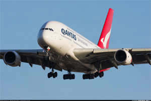
Photo copyright Sebastian Lukasiewicz - used with permission
Qantas Flight 32, VH-OQA
Batam Island, Indonesia
November 4, 2010
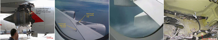
On November 04, 2010, Qantas Flight 32, an Airbus 380 operated by Qantas Airways Ltd, departed Changi Airport, Singapore on a scheduled passenger flight to Sydney, Australia. The flight carried 469 passengers and crew. About four minutes after take-off, while the aircraft was climbing through about 7,000 feet over Batam Island Indonesia, the flight crew heard two "bangs." The noises were the result of an uncontained failure of the No. 2 engine, a Rolls-Royce Trent 900 series turbofan. Debris from the engine impacted the aircraft, causing significant damage to the structure and airplane systems and resulted in fuel leakage from the left-wing fuel tank.
The airplane entered a holding pattern and, after 50 minutes of completing procedures and performing progressive aircraft controllability checks, the flight crew landed the aircraft safely at Changi Airport. Following landing, the No. 1 engine could not be shut down. With the No. 1 engine still running, and with flight crew concerns about leaking fuel and potential passenger injuries, passenger offloading was delayed for approximately an hour. Offloading was completed approximately one hour after offloading began (two hours after landing), using a single cabin exit. The No. 1 engine was successfully shut down three hours after landing by spraying firefighting agent into the engine inlet.
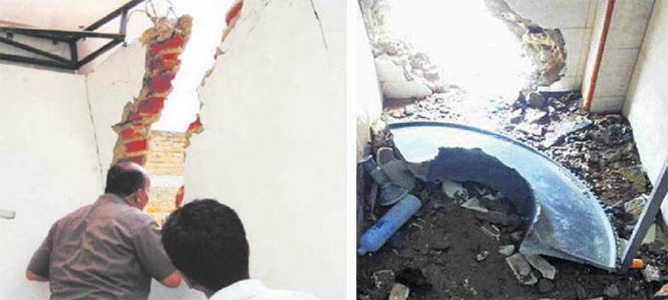
The accident investigation determined that the probable cause of the engine failure was a manufacturing error involving an internal oil feed stub pipe. The oil feed pipe was manufactured with a reduced wall thicknesses that eventually cracked and caused oil spray leakage and fire in the High Pressure/Intermediate Pressure (HP/IP) bearing support hub assembly. The fire weakened the intermediate turbine drive arm, which subsequently fractured, allowing the IP turbine disk to overspeed and break apart. High speed engine debris penetrated many areas of the airplane, including damage to buildings beneath the flight path. There were no reported injuries to the passengers, crew, or persons on the ground.
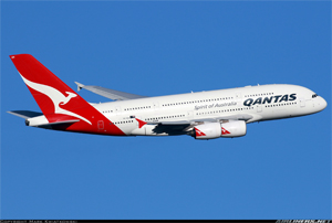
Photo copyright Mark Kwiatkowski - used with permission
History of Flight
On November 04, 2010, Qantas Flight 32, an Airbus A380 powered by four Rolls-Royce Trent 900 engines and operated by Qantas Airways Ltd, departed Changi Airport, Singapore on a scheduled passenger flight to Sydney, Australia. Onboard were five flight crew, 24 cabin crew and 440 passengers. About four minutes after take-off, while the aircraft was climbing through approximately 7,000 feet over Batam Island, Indonesia, the flight crew heard two "bangs." The noises were the result of an uncontained engine rotor failure (UERF) of the No. 2 engine. Debris from the engine impacted the aircraft, resulting in significant damage to the aircraft structure and systems and caused fuel leakage from left wing fuel tank.
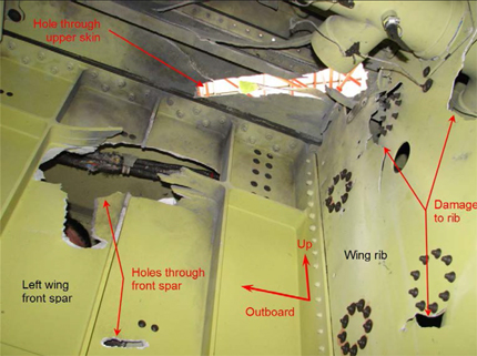
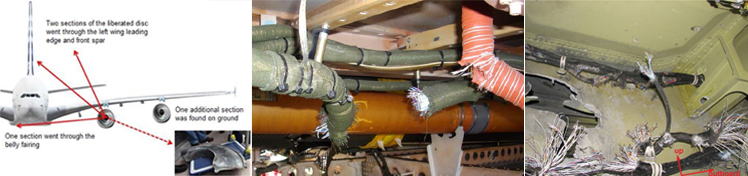
Immediately following the engine failure and resulting aircraft damage, a number of system warnings and cautions were displayed on the electronic centralized aircraft monitor (ECAM). Initially, the ECAM displayed a turbine overheat warning for the No. 2 engine. Engine debris had impacted the aircraft, resulting in significant structural and systems damage. A large fragment of the turbine disc penetrated the left wing leading edge before passing through the wing front spar into the left wing fuel tank and exiting through the top skin of the wing. The fragment initiated a short-duration, low-intensity flash fire inside the fuel tank. Ambient conditions within the tank were not suitable to sustain the fire. A large fragment of the turbine disc also severed electrical wiring inside the wing leading edge. Hydraulic and electrical distribution systems were also damaged, which effected other systems.
View Larger
Subsequent to the engine failure, the flight crew received air traffic control (ATC) clearance to enter a holding pattern, where for 50 minutes they completed ECAM procedures and performed aircraft controllability checks. An assessment of landing distance requirements was accomplished that included consideration for a number of critical system failures (e.g. inoperative wing leading edge devices, inactive number one engine thrust reverser, and a high number of system and flight control malfunctions). A successful approach and landing were completed at Changi Airport.
View Qantas Flight 32 Flight Path Animation below:
Once coming to a full stop, the captain did not order an emergency evacuation. The offloading of passengers was delayed for approximately one hour, as the flight crew was not able to shut down the No. 1 engine. Investigators determined that the captain had been concerned about the still operating No. 1 engine, high brake temperatures, large fuel leaks, and potential injuries to passengers during an evacuation. Believing that firefighting personnel had minimized the danger of a fire, the captain delayed passenger offloading until an air stair could be brought up to the right side of the airplane, opposite from the running engine. Passenger unloading via the air stair required approximately one hour. The No. 1 engine was finally shut down, about three hours after the aircraft landed, by pumping firefighting foam directly into the engine inlet. There were no reported injuries to passengers or crew. There were no confirmed injuries to persons on Batam Island where a large segment of the IP turbine disk fell.
Rolls-Royce Trent 900 Engine
View Larger
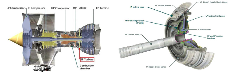
As described in the accident report, "The Rolls-Royce Trent 900 is a three-shaft, high-bypass ratio turbofan engine with variants ranging in maximum thrust from 334.3 kN (75,152 lb.) to 374.1 kN (84,098 lb.). The three primary rotating assemblies in the Trent 900 are:
- a low pressure (LP) compressor (fan) connected by a shaft to a five-stage LP turbine
- an intermediate pressure (IP) compressor connected by a shaft to a single stage IP turbine
- a high pressure (HP) compressor driven by a single-stage HP turbine.
Each rotating assembly is supported by bearings at the front and rear of each shaft."
The accident engine was a Rolls-Royce Trent 972-84 t, with a rated maximum take-off thrust of 76,752 lb.
View Larger
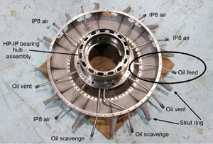
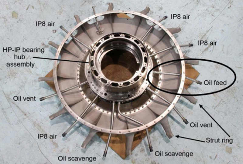
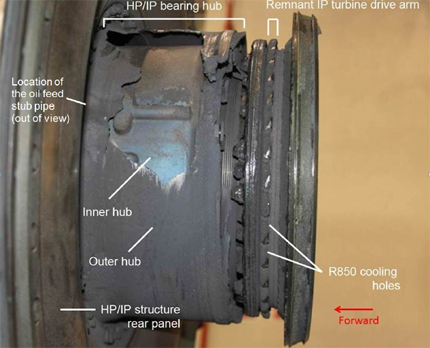
The engine is of modular construction with a separate module for the IP turbine. The IP turbine module consists of the IP shaft, turbine disc and blades, nozzle guide vanes (NGVs), IP turbine case, LP turbine front panel, bearings for both the HP and IP, and their support structure. The bearings are located in a hub surrounding an oil fed chamber, and are connected to the IP turbine case via a ring structure that has a front and rear panel. Support struts pass through the IP turbine NGVs.
(Engine Cross-section – Detailed view).
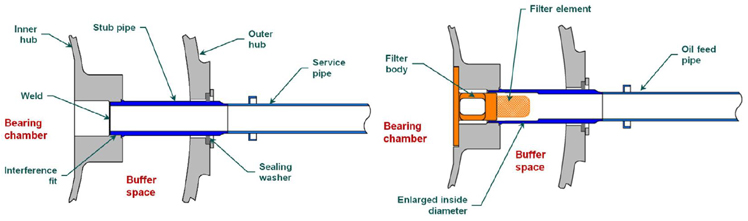
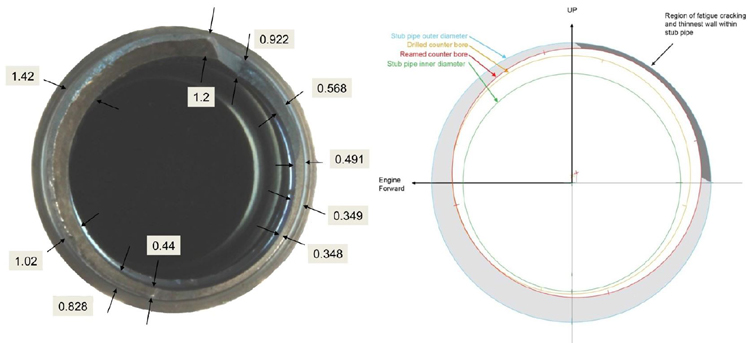
The oil feed, scavenge, and vent pipes pass through the outer hub, then through the buffer space, and are attached to the inner hub via interference fit. These pipes have an extension, referred to as a stub pipe, which includes additional length, allowing the pipe to reach the inner hub. To accommodate an integral filter in the oil feed stub pipe, the inner hub end of that pipe has an enlarged inside diameter.
View Larger
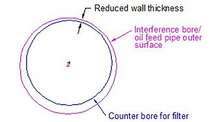
Oil Pipe Manufacturing Error
The oil feed stub pipe within the HP/IP hub assembly was manufactured with insufficient wall thickness. The incorrectly manufactured oil feed stub pipe on the No. 2 engine developed fatigue cracking which led to an oil leak and then an internal oil fire.
View Larger
View Large
Engine Failure Sequence
Investigators determined that the uncontained failure of the IP turbine rotor progressed in five phases:
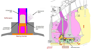
1. Oil feed stub pipe failure and oil fire
Fatigue cracking had developed in the oil feed stub pipe. The cracking grew and on this flight led to an oil leak which atomized and likely auto-ignited about one minute prior to engine failure. Pressures and temperatures in the HP/IP bearing chambers were such that auto-ignition was probable. Temperatures in the bearing chamber were in excess of 365 °C, and the auto-ignition temperature of the leaking oil was as low as 280 °C. Investigators believe that auto-ignition occurred immediately when the leak began.
View Larger
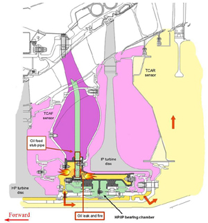
2. HP turbine triple seal failure
About ten seconds before engine failure, the fire breached the front face of the HP/IP bearing chamber and impinged directly on the triple seals. The intense heating distorted the seals, leading to their complete failure and separation from their support structure. When the triple seals were breached, hot gases exiting the HP turbine were drawn into the lower pressure space behind the HP turbine disc.
3. Drive arm heating and disc separation from the drive shaft
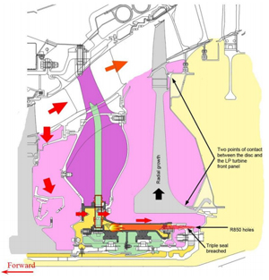
The IP turbine drive arm, via the IP drive shaft, transmits power generated by the IP turbine to the IP compressor. Following the failure of the triple seals, the resulting change in the pressure distribution inside the engine resulted in intense heat and flame being directed onto a second triple seal at the rear of HP/IP bearing chamber. This triple seal also failed, allowing flame to be directed onto the drive arm. The drive arm rapidly heated and then failed, separating the IP turbine from the IP drive shaft. The unrestrained turbine then moved rearwards and contacted the LP turbine front panel.
View Larger
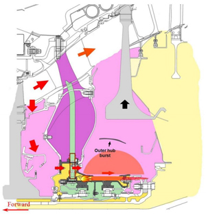
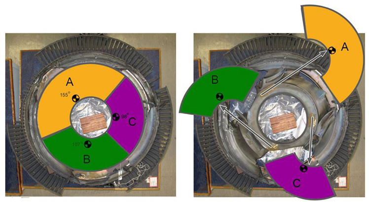
4. Disc acceleration and burst
Immediately after the drive arm failure, HP turbine airflow caused the unrestrained IP turbine disc to accelerate to destruction. The IP turbine disc burst into three pieces, four seconds after failure of the drive arm.
5. Flight crew response leading to engine shutdown
Twenty-nine seconds after the disc separated from the drive shaft, and in response to the ECAM overheat indication, the flight crew reduced thrust on the No. 2 engine to idle. Fifteen seconds later, the thrust lever was advanced and, after an initial thrust increase, the engine surged, whereupon it was shut down by the flight crew.
View Larger
An animation of the failure sequence is available at the following link:
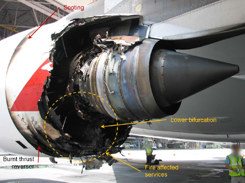
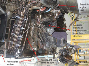
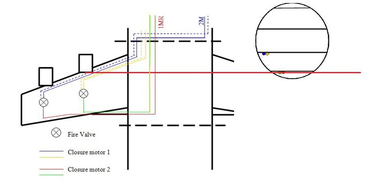
External Fire
View Larger
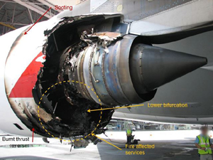
Following the engine failure, an external fire developed in the lower left region of the No. 2 engine nacelle.
View Larger
View Larger
A passenger who was seated on the upper left deck of the aircraft reported observing a fire coming from the hole in the left wing skin that lasted for five to six minutes. None of the flight crew reported being aware of a fire in the left wing. Post-accident examination of the left wing revealed a region of sooting inside the fuel tank. Investigators determined that the passenger had a clear view of the No. 2 engine through the damaged section of the wing. Due to the duration of the fire and location of the passenger, it is believed that the passenger observed the No. 2 engine fire rather than the fuel tank's flash fire.
Airplane System Effects
Engine debris damaged a number of systems. As a result, a number of other systems were impacted. Investigators characterized the bulk of system damage as damage to wiring resulting in various system effects as follows: (Excerpted from accident report)
View Larger
| System | Loss of function or Effect |
|---|---|
| Air conditioning | The bleed air ducts in the left wing leading edge and center fuselage were damaged from impact by the engine debris, affecting the distribution of bleed air from engines No. 1 and 2 and the APU. The damage was detected by the ODS and the affected pneumatic systems were isolated in less than 10 seconds. There was no operational impact. |
| Braking | -Loss of function to the left wing gear brakes -Reduction of function in the right wing gear brakes (including anti-skid) |
| Cabin Systems | Partial loss of bleed air, resulting from damage to the: -Left wing system ducting -APU bleed air ducting |
| Electrical Power | Electrical power, was affected either as a direct result of the damage from the engine failure, or due to actions taken by the flight crew as part of the ECAM procedures: -A loss of electrical power generation at engines No. 1 and 2 -The loss of one of the aircraft's four alternating current (AC) systems -The inability to connect the aircraft's auxiliary power unit (APU) generators on the ground |
| Engine Controls | Auto-thrust function: -Reduction in the automatic control function to engines No. 1, 3 and 4 |
| Engine Fuel and Control | Fuel leakage from the No. 2 engine feed tank -Loss of function to engines No. 1 and 2 low pressure fuel shutoff valves -Loss of function to the No. 1 engine high pressure shutoff valve -Loss of function of numerous fuel system components (valves and/or pumps) -Degradation of the fuel quantity management system -Reduction in capability of the automatic and manual fuel transfer function -Disabling the fuel jettison system -Inability to shut down No.1 engine |
| Fire Protection | -Loss of function to one of the two extinguisher bottles in engines No. 1 and 2 |
| Flight Controls | -Reduced aileron and spoiler function -The loss of wing leading edge slats and droop nose function. |
| Fuel | -Loss of the fuel isolation valves (LPSOV) for the No. 1 and No. 2 engine -Loss of the fire protection system for the No. 1 engine -All means of shutting down the No. 1 engine -Loss of fuel transfer system |
| Hydraulic Power | -Partial loss of green hydraulic system -Reduced redundancy within the aircraft's other (yellow) hydraulic system |
| Ice and Rain Protection | Unspecified |
| Ignition | Unspecified |
| Landing Gear | -Normal extension function was no longer available |
| Lights | Unspecified |
| Oil | Unspecified |
| Pneumatic | See Air-conditioning |
| Water/Waste | Unspecified |
Post Landing Events
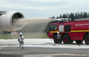
Following landing and after coming to a stop on the runway, the No. 1 engine continued to run at thrust levels above ground idle and could not be shut down. The No. 1 engine was finally shutdown about three hours after landing. Shutdown was accomplished by pumping firefighting foam directly into the engine. Investigators later attributed the inability to shut down the engine to severing of wires in the left wing leading edge and belly fairing of the aircraft which caused loss of control of the No. 1 engine low pressure shutoff valve.
The captain did not order an emergency evacuation. Investigators concluded that the inability to shut down the No. 1 engine, leaking fuel, and hot brakes were a concern to the flight crew. Believing that fire control personnel had minimized the potential for a fire, and amid concerns about the potential for passenger injury, the captain elected to keep passengers on the airplane rather than evacuate. About an hour after landing, passenger offloading was begun using a single exit on the right side of the airplane. Passenger unloading took about an hour and was completed two hours after landing.
The Australian Transportation Safety Board (ATSB) issued 32 findings over a range of subjects. The complete text of the findings is available at the following link: (See Section 6 Findings)
The complete ATSB accident report is available at the following link: (ATSB Transport Accident Report)
The ATSB issued three formal safety recommendations. However, the ATSB process for issuance of safety recommendations is different than some other investigative agencies. The ATSB defines Safety Issues and describes those issues in the Findings section of the accident report. If an authority, manufacturer, or other agency takes proactive action, the ATSB evaluates that activity relative to the defined safety issue. If the action is determined satisfactory, the ATSB does not issue a recommendation. Section 7 of the accident report describes all actions taken by the engine and airplane manufacturers and suppliers, EASA, ATSB, FAA, and the NTSB.
In addressing any recommendations, the ATSB also includes the resolution actions, and determines if those actions are satisfactory. A document containing just the issued safety recommendations, and extracted from Section 7 of the accident report, is available at the following link: (ATSB Recommendations)
In order to provide context for the recommendations, and to include a comprehensive list of the resolution activities investigated by the ATSB, Section 7, copied directly from the accident report, is presented in its entirety at the following link: (ATSB Safety Actions)
Airplane Airworthiness Regulations
European (EASA/JAA) Regulations
US (FAA) Regulations
14 CFR §25.901 (c) Installation
Engine Airworthiness Regulations
European Regulations
US Regulations
Advisory Material
Airplane
EASA AMC 25.901(c) Safety Assessment of Powerplant Installations
FAA Advisory Circular 20-128A (Part 1) (Part 2) Design Considerations for Minimizing Hazards Caused by Uncontained Turbine Engine and Auxiliary Power Unit Rotor Failure
Engine
EASA/JAA ACJ E 210 Failure Analysis
EASA/JAA ACJ E 810 Compressor and Turbine Blade Failure
EASA/JAA ACJ E 840 Rotor Integrity
FAA Advisory Circular AC 33.75 Safety Analysis
Quality Control Process Lapse
Rolls-Royce discovered that a number of oil feed stub pipes had been incorrectly manufactured (non-concentric counter bores) and delivered on engines. Other oil feed stub pipes with non-concentric counter bores were also found in the factory, prior to installation on engines. A statistical analysis was performed using the not-yet- delivered parts, and the results of that analysis were extrapolated to include the parts already in service. Based on the results of that analysis, it was determined that the oil feed stub pipes that were already in service did not need to be recalled or replaced.
Investigators determined that an expert review of the nonconformance issues had not been performed, nor was it required for review of what was termed” retrospective concession applications.” Further, investigators noted that the manufacturer’s processes did not specify when the Chief Engineer and Business Quality Director approvals were required. Both of these items were identified as safety issues by the investigators. Investigators also noted that by not providing the opportunity for the Chief Engineer or Business Quality Director to review and approve the analyses associated with retrospective concessions, it prevented those parties from assessing the potential impact on the in-service fleet.
Manufacturing Process Lapse
Finally, investigators stated in the accident report that since the manufacturing errors took place over at least three years, it was likely that, “…… a culture existed ……… that considered that not strictly adhering to the nonconformance management procedures in the group quality procedures was a viable form of behavior. Specifically, it was considered acceptable to release parts with undeclared non-conformances that were considered by at least some of the inspectors to be ‘minor’. “
- The manufacturing non-conformity leading to failure of an oil feed stub pipe, initiation of an internal oil fire, and subsequent uncontained engine failure.
- The failure mechanism intended by the design (aft translation of the IP turbine disc) to prevent an uncontained failure of the IP disc did not function as designed.
- The manufacturing non-conformity related to the failed oil feed stub pipe was "assessed to have no effect on the customer."
- Aft translation of a liberated IP turbine would lead to contact with stationary structure and prevent an uncontained failure.
As part of the process for cataloging findings and issuing safety recommendations, the ATSB identified a number of safety issues. Safety issues, for which resolution activity undertaken by the engine or airplane manufacturer were considered to be satisfactory, were closed by the ATSB and subsequent safety recommendations were not developed. Among the actions taken by Roll-Royce, Airbus, and EASA are:
Actions taken by Rolls-Royce:
- Rolls-Royce incorporated a software change in the Engine Electronic Controller (EEC) to introduce an IP turbine overspeed protection system.
- Rolls-Royce, after discovery in the A380 fleet of a number of oil feed stub pipes that were non-conforming, undertook a detailed analysis of those stub pipes, removing 40 engines from service and revising the minimum stub pipe wall thickness from .5 mm to .7 mm.
- Rolls-Royce introduced new processes that required closer coordination between manufacturing engineers and design engineers to reduce manufacturing errors and maintain criteria for acceptance/rejection of non-conforming stub pipes.
- Rolls-Royce reclassified the HP/IP bearing support structure to identify it as being "reliability sensitive," which invoked a higher level of process control during manufacture and installation.
Actions Taken by Airbus:
- In response to Rolls-Royce's action to incorporate an EEC software revision which introduced an IP turbine overspeed protection system, Airbus issued a service bulletin to incorporate the software revision on all Trent-equipped A380 airplanes.
Actions taken by EASA:
- EASA released an airworthiness directive 2010-0262 to require, within ten flights, an EEC software revision to incorporate an IP turbine overspeed protection per a Rolls-Royce service bulletin.
A complete list of safety actions undertaken after the accident is included in the following document, which is extracted from the official accident report: (Follow-on Safety Actions)
This document provides more detail, and a complete list of safety actions taken following the accident.
Additionally, Section 7 of the ATSB report "Safety Action" details all safety activity related to this accident and details the relationships between ATSB safety issues and resolution activity. This section of the report is provided in its entirety at the following link: (Section 7 Safety Actions)
- AD 2010-0236-E Issued November 10, 2010, by the European Aviation Safety Agency (EASA). This emergency AD required the periodic inspection of the HP/IP engine structure for any abnormal oil leakage.
- AD 2010-0242-E Issued November 22, 2010, and superseded AD 2010-0236-E. This new AD amended the inspection procedures of the superseded AD and required inspections per Rolls-Royce Alert Service Bulletin NMSB 72-AG590 Revision 2.
- AD 2010-0262 Issued December 13, 2010, requiring modification of Trent 900 EEC software to incorporate IP turbine overspeed logic as detailed in Rolls-Royce Service Bulletin NMSB RB.211-73-AG639. Modification of all Trent 900 engines was required within ten flight cycles.
- AD 2010-0242R1 Issued December 21, 2010, revised the inspection procedures of AD 2010-0242-E.
- AD 2010-0242-CN Issued March 2, 2011, cancelled AD 2010-0242R1, citing the intrusive nature of the previously mandated inspections and the need for the AD having been overtaken by the issuance of AD 2010-0262.
- AD 2010-0262-CN Issued April 15, 2016, cancelled AD-2010-0262. The reason for cancellation states that all affected engines have been satisfactorily modified per AD 2010-0262, thereby cancelling the need for the AD.
Airplane Life Cycle:
- Design / Manufacturing
Accident Threat Categories:
- Uncontained Engine Failure
- Uncontrolled Fire / Smoke
Groupings:
-
N/A
Accident Common Themes:
- Organizational Lapses
- Flawed Assumptions
- Pre-existing Failures
Organizational Lapses
The engine manufacturer did not provide guidance to manufacturing personnel on how to determine the significance of manufacturing escapes. Quality control personnel identified a manufacturing error that had been made in approximately 100 oil feed stub pipes after the non-conforming parts had been installed on engines in service. However, there were no adequate processes provided to determine or establish the significance of the manufacturing error. An analysis determined that the incorrectly manufactured parts were adequate for installation. Once entering service, one of the incorrectly manufactured parts failed on the accident flight, leading to an uncontained engine failure.
Flawed Assumptions
A fundamental design assumption was that in the event of an IP turbine drive arm failure, the IP turbine assembly would translate aft and contact stationary structure, mitigating the potential for an IP turbine overspeed event. In this accident, the IP turbine continued to accelerate after failure of the drive arm, resulting in failure of the IP turbine disc.
National Airlines Flight 27, McDonnell Douglas DC-10, November 3, 1973
While cruising at 39,000 feet, the No. 3 engine fan assembly completely disintegrate. The inlet and fan case separated simultaneously, liberating fan blades which struck the fuselage causing failure of a cabin window and expelling a passenger who was fatally injured. This accident is located in this library at the following link: (National DC-10)
See accident module
United Airlines Flight 232, McDonnell Douglas DC-101, July 19, 1989
During cruise, the fan disc in the No. 2 engine fractured due to a fatigue crack that occurred as a result of a manufacturing defect. Engine debris penetrated structure in the aft portion of the airplane and caused the loss of all hydraulic systems. The flight crew exercised minimal control of the airplane using asymmetric thrust and were able to attempt an approach in Sioux City, Iowa. Control was lost just before landing and the airplane crashed near the runway. This accident is located in this library at the following link: (United Flight 232).
In 1995, a DC-9 suffered a seventh stage HPC disk failure on takeoff roll which severed a fuel line and resulted in a hull loss. There were no fatalities.
See accident module
Delta Air Lines Inc. Flight 1288, McDonnell Douglas MD-88, July 6, 1996
As the airplane was beginning its takeoff roll, the fan hub on the No. 1 engine fractured, sending engine debris into the fuselage. The fan hub failure was the result of a fatigue crack in a hole that had been improperly drilled and finished during manufacture. This accident is located in this library at the following link: (Delta 1288)
See accident module
Edelweiss Air Flight 656, Airbus Industrie A330-200, October 5, 2003
The airplane experienced an uncontained turbine blade release from the No. 1 engine. The flight crew declared an emergency and returned to Miami, FL. Investigation revealed that the intermediate pressure (IP) turbine case was ruptured 360° circumferentially and that the IP turbine disk had separated from its drive arm, resulting in the liberation of all the IP turbine blades
An overspeed condition, likely the consequence of the drive arm failure, resulted in the liberation of all IP turbine blades, which passed through the IP turbine case, some blades striking the airplane.
TAM Airlines flight 9755, Fokker F100, September 15, 2001
During cruise, the No. 2 engine, experienced an uncontained failure. Engine debris penetrated the cabin, causing a passenger to be partially expelled through a window and a rapid decompression of the cabin. The airplane was successfully landed, and no other passengers were injured.
British Airways Flight 2276, Boeing 777, Sept. 9, 2015
During takeoff roll, the airplane experienced a failure in the high-pressure compressor of the No. 1 engine. The airplane was able to be stopped on the runway and a large ground fire erupted. Passengers and crew were successfully evacuated.
Technical Related Lessons
Airplane level hazards associated with an uncontained engine failure are mitigated by the combined safety strategies for both the engine and airplane. This is accomplished by:
FOR THE ENGINE - Engine design, manufacturing, and maintenance programs are developed and implemented in order to achieve the lowest possible risk of experiencing an uncontained engine failure.
FOR THE AIRPLANE - Airplane design, manufacturing, maintenance, and operation programs are developed and implemented in order to minimize hazards to the airplane should an uncontained engine failure occur. (Threat Category: Uncontained Engine Failure)
- In this accident, investigators learned that the oil feed stub pipe had been manufactured out of conformance with the approved design and installed on the accident engine. Once the accident engine entered airline service, fatigue cracks developed in the oil feed stub pipe, resulting in an internal oil leak and fire that progressed into an uncontained engine failure.
- The A380 accident airplane experienced damage to airplane structure and systems from the uncontained engine debris. In spite of the extent of damage, continued safe flight and landing was accomplished. Investigators attributed this to system isolation and redundancy which mitigated the associated hazards and allowed the flight to continue to navigate, control the flight path, and land safely.
For turbine engines, certain types of lubrication system failures or malfunctions have the potential to damage highly loaded rotating machinery, and in some cases can lead to uncontained engine failures. (Threat Category: Uncontained Engine Failures)
- Lubrication system failures can result in a series of cascading failures that have the potential to result in catastrophic airplane effects. In this accident, an oil feed stub pipe in the intermediate pressure turbine section developed a fatigue crack which over time progressed into an atomized oil leak. The leaking oil was being introduced into a high temperature area and was determined by investigators to have autoignited and compromised the triple blade seal in the IP turbine bearing chamber. Once the blade seal was destroyed, fire rapidly progressed into a lower pressure region of the engine, rapidly heating nearby components and destroying the IP turbine drive arm. Once the IP turbine disc separated from the drive arm, the IP turbine oversped and burst into three pieces. Pieces of the ruptured disc penetrated the wing and created a fuel leak which continued until after landing. Investigators concluded that the progression of events, from initiation of the oil leak, and culminating in the uncontained rotor burst elapsed over approximately one minute.
Fuel tank breaches pose an extremely hazardous condition for passenger safety and can very quickly develop into external fires than can lead to injuries and loss of life. (Threat Category: Uncontrolled Fire/Smoke)
- In this accident, the captain did not order an emergency evacuation. The flight crew was concerned with the combination of a fuel leak, fuel pooling under/around the airplane, hot brakes, and the potential for passenger injury during an evacuation. Fire and rescue personnel were at the airplane, applying firefighting foam to the undercarriage. Believing that the potential for fire was under control, the captain elected to keep the passengers on board the airplane until fire and rescue personnel had completely mitigated the fire threat.
- A fuel system breach can easily result in ignition, and thus, fire or explosion. Large fuel leaks have quickly led to external fires resulting in loss of life and/or airplane hull loss. Although the process involved in the ignition of jet fuel vapors is complex, post-accident fuel ignition can generally be attributed to two causes:
- Hot surface ignition: This is the auto-ignition temperature of a substance and is the lowest temperature at which it spontaneously ignites. For most jet fuels, this temperature can be as low as 400 degrees F. A post-accident aircraft can have many surfaces well above this temperature, such as turbine engine tailpipes and aircraft brakes.
- Electrical arcs: This ignition process is usually related to the fuel vapor flammability envelope and is also influenced by ambient temperatures and pressures. For Jet-A fuels, vapor ignition can take place at extremely low spark energy levels, and in some conditions, with a spark as little as one thousandth of a Joule, or less. Such a small spark is barely visible to the human eye. Damaged wiring can easily involve sparking with energies well above these levels.
Common Theme Related Lessons
Risk management processes relative to manufacturing escapes/non-conformities should be consistently applied regardless of the delivery status of the parts in question. (Common Theme: Organizational Lapses)
- Rolls-Royce discovered that 100 oil feed stub pipes had been produced with misaligned counter bores, potentially thin pipe walls, and released into service. Investigators stated that a process to assess the degree of non-conformance (or significance of a manufacturing error on the integrity of the stub pipe) for parts that had already entered service did not exist. A statistical analysis was performed on nine stub pipes that were in process in the factory, and it was determined, based on the results of the study, the 100 pipes already in service could remain in service. Additionally, as stated in the accident report, the non-conformance "was assessed to have no effect on the customer." As a result, the 100 affected stub pipes were not retrieved and remained in service.