
Cessna T310Q
Private Pilot, N301JA
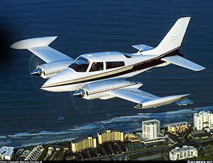
Source: Mariano Rosales, Airliners.net
Wichita, Kansas
September 25, 2015
At 1550 Central Time on September 25, 2015, a Cessna T310Q, N301JA, departed Wichita Dwight D. Eisenhower National Airport in Wichita, Kansas bound for Centennial Airport in Denver, Colorado. The personal flight was conducted under Title 14 Code of Federal Regulation Part 91. An instrument flight plan was filed, and visual meteorological conditions prevailed at the departure airport. After takeoff and during the initial climb, the aircraft experienced a flight control malfunction, pitched down abruptly, and impacted the terrain two miles northeast of the airport. The aircraft was destroyed and the pilot, the sole occupant, was fatally injured.
The National Transportation Safety Board (NTSB) determined the probable cause of this accident to be the separation of the attachment hardware connecting the elevator trim tab pushrod to the elevator trim actuator. This resulted in the trim tab jamming in a position outside the normal range of travel and subsequent loss of aircraft control.
NTSB report: CEN15FA425
History of Flight
Source: FlightAware
On September 25, 2015, the accident aircraft departed runway 01R at Dwight D. Eisenhower National Airport in Wichita, Kansas. The afternoon flight was to be a personal, cross-country trip to Centennial Airport in Denver, Colorado. The pilot had filed an instrument flight plan and visual meteorological conditions prevailed at the departure airport.
A flight control malfunction occurred during the initial climb after takeoff that caused the elevator trim tab to become jammed in a position which was three times the normal amount of its deflection. This resulted in the aircraft abruptly pitching down, entering a rapid descent until impacting the ground, fatally injuring the pilot. One witness stated, "the airplane appeared to be flying normally, and then it suddenly pitched down and entered a rapid descent." Other witnesses described the descent angle as "greater than 45 degrees" and "50 to 70 degrees" with the engines sounding like they were at full power.
The aircraft came to rest in trees, ground, and a creek two miles northeast of the airport. Parts of the aircraft were found on the banks of the creek and others were submerged in the creek. The fuselage was severely damaged from the aft baggage compartment to the nose, while the section of fuselage from the aft baggage compartment to the tail was intact but heavily damaged. Post-accident investigation led to the discovery that the nut and bolt securing the trim actuator to the elevator trim tab pushrod were missing and never recovered at the crash site.
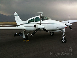
Source: Toshiro Hara, Airliners.net
Cessna 310
The Cessna 310 first flew on January 3, 1953 and was certificated on March 22, 1954. Production immediately followed and continued through 1980, producing 5,449 aircraft. Cessna built twin-engine aircraft during World War II, but the 310 was their first twin-engine aircraft they produced in the post war years. Although being designed for military wartime operations and conditions, many surplus military twin-engine aircraft could be purchased inexpensively and were converted to executive transports during this period. Despite being economical to acquire, the operation and maintenance for these machines were costly. Cessna realized a strong market need for a new, purpose-built twin for the business flyer.
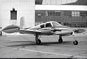
Source: John Stoll
Early Cessna 310s were equipped with two 240 HP engines, a straight tail, and round wingtip fuel tanks. Over the years various models were made to include increases in horsepower, turbocharging, changes to the nose, wingtip tanks, windows, and slanting the tail. An early-model Cessna 310 became a television star with a feature role in the TV series "Sky King," a popular show from the 1950s. Several countries, including the United States, operated a military version of the aircraft.
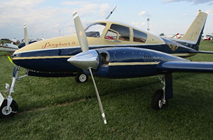
Popularity of piston twin-engine aircraft has declined over the years. Business use has transitioned to more economical aircraft, but owners still consider the 310 an excellent cross-country aircraft and it remains popular among piston twin-engine owners. Cessna ended production of the Cessna 310 in 1981, but a large number are still registered. The accident aircraft was a 1972 Cessna T310Q model, which had its last annual inspection on May 8, 2015. The pilot registered the aircraft September 26, 2014, almost a year before the accident.
Aircraft Hardware
Source: John Stoll
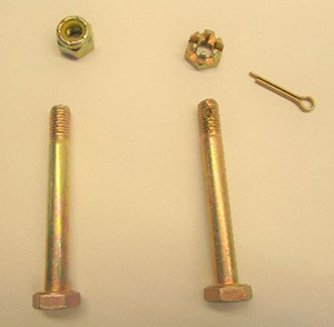
Aircraft nuts and bolts come in a variety of material strengths, sizes, shapes, and uses for specific applications. These nuts and bolts are not suitably replaced by purchasing them at the local hardware store, as they must be selected to handle the specific loads for their application.
Commonly, aircraft nuts and bolts can be loaded in tension, shear, or bending. If the bolt is used as a hinge, small torsional forces can be applied. There are different methods to secure the hardware so that it does not loosen in operation. Locking aircraft nuts can be divided into two basic groups: self-locking and non-self-locking nuts. The corresponding bolts either have a drilled or un-drilled shaft, as appropriate.
Self-locking nuts have an integral feature, an elastic material such as nylon, fiber, or crimped metal threads that provides friction to the threads of the bolt to prevent loosening. The fiber or nylon locking collar is not threaded and is smaller than the diameter of the threaded portion of the nut. As the bolt is screwed through the nut and enters the elastic collar, the friction of the bolt threads against the elastic material, causing the material being pushed upward to compress, resulting in the resistance of elastic material creating a heavy downward pressure.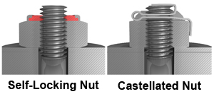 This pressure remains constant as the bolt is threaded through the nut. There is also an inward-directed radial pressure on the threads of the nut which, in combination of the downward pressure, locks and holds the nut securely in place.
Self-locking nuts that require a secondary locking feature are known as dual-locking nuts. They are primarily used on parts subject to rotation. Acceptable practices dictate that where the joint is subject to rotation, or for any parts that are routinely disassembled, the use of self-locking nuts should be avoided.
All-metal, self-locking nuts are to be used in areas where temperatures exceed 250°F in lieu of the fiber and nylon self-locking types because the heat may soften or melt the elastic material. Self-locking nuts may be reused if the elastic material has not become brittle or has not lost its locking friction. FAA Advisory Circular 43.13B "Acceptable Methods, Techniques and Practices-Aircraft Inspection and Repair" provides minimum torque values, but a rule of thumb is if the nut can be finger tightened, it should be replaced.
Source: John Stoll
Non-self-locking nuts can include the castellated (castle) nut, the castellated shear nut, the plain hex nut, and plain check nut (jam nut). Castellated nuts look like a miniature castle, thus the name castle nut. Castle nuts are designed to receive a cotter pin that goes through the slots, (called castellation), then through the drilled shank in the bolt, and through the opposite side castellation where it is bent over, physically locking the nut in position. The cotter pin is a one-time use item and needs replacement each time it is removed. Plain hex nuts use an auxiliary locking device such as a lock washer or check nut.
Source: John Stoll
Trim Systems
Source: Aviation Maintenance Technician Handbook – Airframe
Aircraft have a large range of airspeeds, altitudes, and power settings where they may be operated. Each combination needs the control column to be in a specific position, requiring physical effort from the pilot to hold it there. Without a system to relieve the resultant control system pressures, the pilot would become fatigued. For this reason, trim systems are designed to aerodynamically assist the movement and position of flight control surfaces, balancing the aerodynamic forces and minimizing the pilot's effort holding the control column.
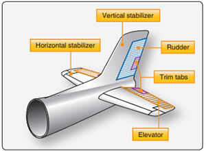
On small aircraft, trim tabs are commonly installed as a single-hinged tab attached to the trailing edge of the elevator. A pilot establishes the desired power setting, pitch attitude, and configuration, and then adjusts the trim to relieve any control pressures for hands-off flight for that flight condition. If the pilot needs to hold constant forward pressure on a control column, they need to add more nose-down trim. Anytime the pilot makes a power, pitch, or configuration change, it is necessary to adjust the trim to relieve the control pressures for the new flight condition. An understanding of Bernoulli's Principle and the lift equation can explain why this happens.
Bernoulli's Principle states that as a wing (airfoil) moves through the air, the flow of air hits the leading edge of the wing where it splits and is forced to travel over the top or bottom of the wing. Regardless of its path, it arrives at the trailing edge of the wing at the same time. Air must travel farther across the top of the wing than for the bottom of the wing due to the shape of the airfoil. For the air over the top of the wing to travel a farther distance yet arrive at the same point as air moving a shorter distance under the wing, the air over the top of the wing must travel at a higher velocity than the bottom. This higher velocity air moving over the curved top surface creates a low-pressure area. The lower pressure on top and the higher pressure on the bottom generates lift. The lift equation is used to analyze this relationship between velocity and lift generation.
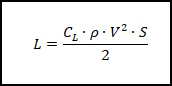
When examining the equation, lift (L) is determined through the relationship of the coefficient of lift (CL) for a given airfoil, the air density (ρ), the airplane velocity (V), and the surface area of the wing (S).
The coefficient of lift (CL) is determined by wind tunnel testing on the airfoil of the wing at a given angle of attack (AOA). The AOA is the angle made between the relative wind and the chord line of the wing. As AOA increases so does the coefficient of lift, up to a point called the maximum coefficient of lift. Beyond that point, any further increase stalls the wing.
Inflight the pilot controls the angle of attack of the wing by manipulating the elevator of the airplane to change the pitch about the lateral axis. For illustration, consider a basic wing airfoil in level flight where the coefficient of lift (CL) at a given AOA, the area of the wing (S), and the density (ρ) are constant. If the aircraft were to then accelerate in level flight, velocity would increase and result in an increase in lift. The generation of resultant excess lift would cause the aircraft to climb and the pilot would need to apply forward pressure on the controls to hold level flight. The forward pressure moves the elevator trailing edge down and creates a nose-down pitch moment. This lowers the AOA of the wing, thus decreasing CL, offsetting the increase in velocity and resulting in the necessary amount of lift to maintain level flight. Therefore, re-trimming is necessary after any power, pitch attitude, or configuration change to relieve control pressure for the new flight condition.
Source: Pilot’s Handbook of Aeronautical Knowledge
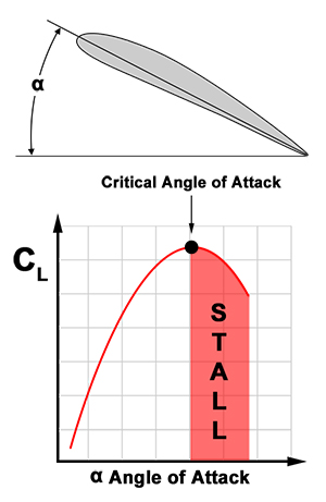
From the figure showing the nose-down trim, if the pilot applies nose-down trim, the trim tab moves opposite to the direction of the elevator. The air flowing over the horizontal tail surface strikes the tab and the trailing edge of the elevator is forced down, thus decreasing the AOA of the leading edge of the wing. The more the trim tab deflects, the greater the nose down force. Nose-up trim would be the reverse; the trim tab deflects downward, the elevator moves up, and the aircraft pitches nose up, increasing the AOA on the leading edge of the wing.
Control surfaces, such as trim tabs, if not properly designed, are susceptible to an aero-elastic process referred to as flutter, which is an unstable oscillation or vibration of the control surface. Flutter may lead to failure of the control surface, its attachment point, or the entire aircraft. Regulation changes for aircraft design requirements for the prevention of flutter that came years after the accident aircraft was built now require that the trim tab be either mass balanced or have dual load paths (connected at two points). With dual-load paths, the failure of one path would leave the other connected and able to move the control surface. If the accident aircraft had been designed with a dual-load path trim control system, the accident may not have occurred. Flutter was not a causal factor in this accident and therefore is not discussed further.
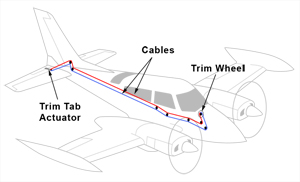
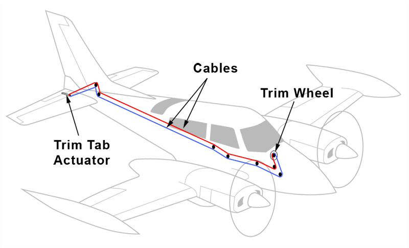
Cessna 310 Trim System
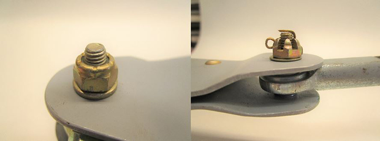
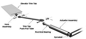
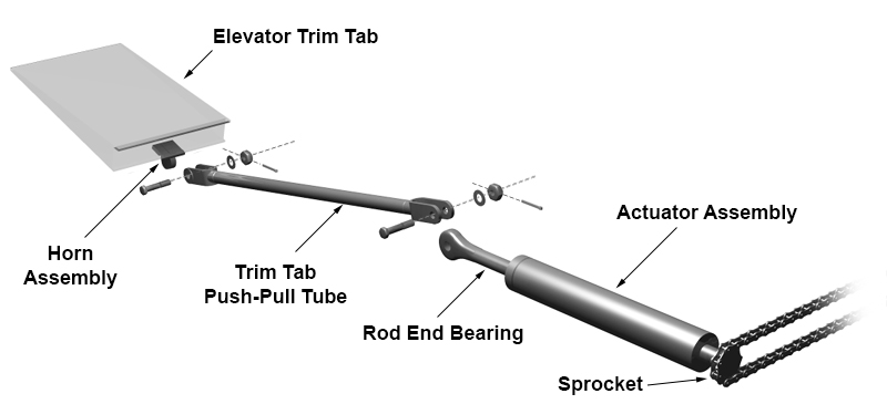
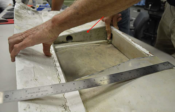
The Cessna 310 pitch trim system is controlled by a trim wheel in the cockpit. The trim wheel is connected to two cables that run over a series of pulleys back to the tail. The ends of the cables are attached to a small chain that wraps around a sprocket on the end of the actuator. Rotating the trim wheel forward or back moves the cable and causes the chain to rotate clockwise or counterclockwise over the actuator sprocket. The actuator has an internal threaded rod that advances or withdraws the actuator rod end bearing depending on which way the sprocket is turned. The rod end bearing is connected by a single nut and bolt to the trim tab push-pull tube, which is then connected at the other end in the same manner.
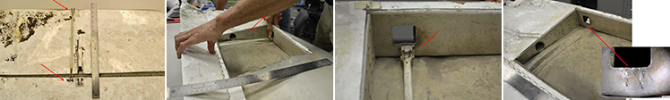
At the accident site, investigators discovered that the trim tab actuator rod end bearing was disconnected from the trim tab push-pull. Investigators conducted a ground search to locate the missing nut and bolt but did not find them. The right elevator was damaged and distorted but remained partially attached to the horizontal stabilizer. The trim tab was attached to the elevator, and the trim tab push-pull tube remained attached to the trim tab horn assembly attach point. The actuator remained attached to the horizontal stabilizer and was found to be extended to a position outside of normal limits.
View Larger
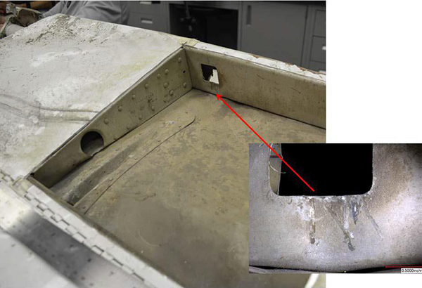
The design of Cessna's elevator trim tab system necessitates a square cutout to be made in the central axis of the elevator spar. This is to allow the trim tab push-pull tube to pass through the spar and connect to the actuator rod end bearing located in the horizontal stabilizer. For the elevator spar to remain stiff enough for flight loads, there must be reinforcing material above and below the cutout. After the loss of the hardware that secured the trim tab push-pull tube to the actuator rod end bearing, the movement of the elevator or trim tab eventually allowed the detached trim tab push-pull tube to pass through the cutout in the elevator spar and fall inside the elevator. The pushrod then moved around inside the elevator but could not pass back through the cutout, ultimately becoming jammed. In the jammed position, the trim tab was deflected to a higher angle than the flight control envelope for which the aircraft was designed and resulted in an unrecoverable nose-down dive.
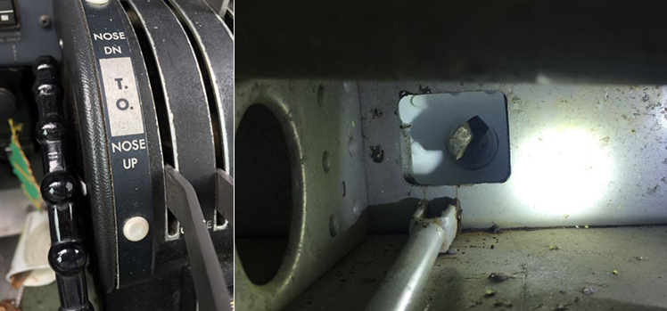
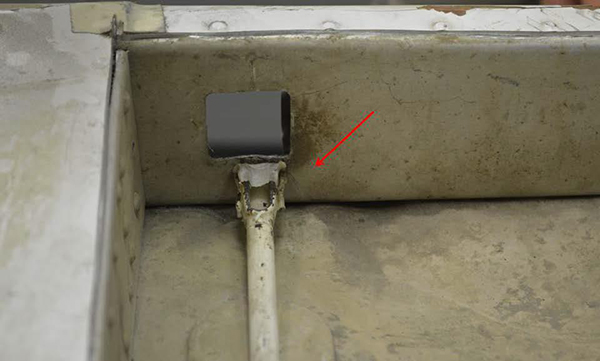
Photo inside the right elevator depicting the trim tab push-pull tube separated from the actuator rod end bearing. Note the rod aft of the actuator and main spar of the elevator. (right)
Source: NTSB
Investigators took the elevator, trim tab, and actuator to Cessna’s laboratory for further examination. They removed a portion of the upper elevator skin and saw gouges and scratches, called "witness marks," on the elevator leading edge spar. There were corresponding witness marks found on the trim tab push-pull tube and actuator that were consistent with the trim tab push-pull tube moving back and forth. Witness marks on the aft side of the elevator spar aligned with the disconnected trim tab push-pull tube end hitting the back side of the spar, which is a position that results in jamming.
Source: NTSB
Due to the damage of the elevator and trim tab of the accident aircraft, investigators used identical parts from another Cessna 310 to obtain measurements. With a properly connected trim tab, a fully extended actuator deflects the elevator trim tab about 12° trailing edge up (TEU). With the elevator trim tab in the TEU position, it produces an airplane nose-down pitching moment by pushing down on the trailing edge of the elevator. With the trim tab push-pull tube disconnected at the actuator and positioned against the aft side of the elevator spar, the elevator trim tab deflected 39° TEU. With the trim tab push-pull tube jammed in this position, it created more than three times the normal maximum TEU deflection. The NTSB concluded that, "The airplane nose-down pitching moment at this increased deflection would create a forward force on the control yoke that a pilot would likely not be able to overcome."
Source: NTSB
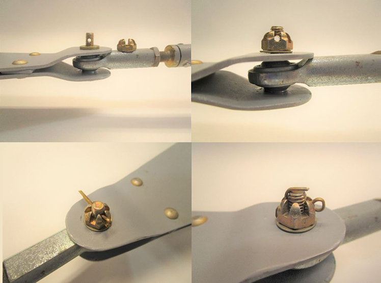
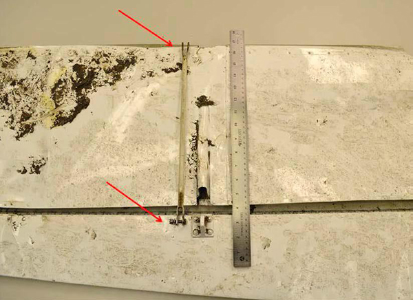
Image1 (View Larger) - Bottom side of right elevator showing the trim tab push-pull tube and tab alignment with the push-pull tube placed outside of the elevator and tunnel. The tab is at the bottom of the photograph.
Image2 (View Larger) - The end of the trim tab push-pull tube is placed behind the elevator spar. The tab is deflected up pulling the trim tab push-pull tube, well past the limits of normal travel. The top side of the elevator skin has been removed.
Image3 (View Larger) - Forward end of trim tab push-pull tube touching the aft side of the elevator spar. This was the position where it jammed.
Image4 (View Larger)- Witness marks on the aft side of the elevator spar that match the forward end of the trim tab push-pull tube. The inset photo provides a detailed view of the scrape marks.
Conclusion
This accident was the result of the loss of a single nut and bolt which caused the elevator trim tab to become jammed, putting the aircraft into a nosedive. This accident could have been prevented had the owner, or previous owners of the aircraft, complied with the Multi-Engine Service Letters the Cessna Aircraft Company produced. One service letter was to inspect and replace the self-locking fastener in the control system while the other service letter was to perform the trim tab actuator inspection. The service letter prescribed a lubrication/inspection interval of 1,000 hours or three years, whichever came first. The mechanic must remove the trim actuator to lubricate and inspect which requires removal of the attaching hardware and re-securing it using a castellated nut, bolt, and cotter pin.
A review of the aircraft logbooks from 2006 through 2015 provided no entries of maintenance actions performed on the elevator trim tab system. Manufacturers use service bulletins or letters to rectify issues or enhance safety in their designs, but because they are not mandatory, they are sometimes unheeded by owners, potentially with catastrophic outcomes.
The NTSB determined the probable cause of this accident to be the separation of the attachment hardware connecting the elevator trim tab pushrod to the elevator trim actuator, which resulted in the elevator trim tab jamming in a position outside its normal travel and a subsequent loss of aircraft control.
NTSB report: CEN15FA425
This accident involves factors in both control system design and the selection of hardware. The Cessna 310 certification basis used the Civil Air Regulations Part 3 (CAR 3) rules which predates the current Title 14 Code of Federal Regulations (CFR) Part 23. The relevant rules governing the design of control systems at the time required the following:
§ 3.328 Installation. Movable tail surfaces shall be so installed that there is no interference between the surfaces or their bracing when each is held in its extreme position and all others are operated through their full angular movement. When an adjustable stabilizer is used, stops shall be provided which, in the event of failure of the adjusting mechanism, will limit its travel to a range permitting safe flight and landing.
§ 3.337 Trimming controls. Proper precautions shall be taken against the possibility of inadvertent, improper, or abrupt tab operations. Means shall be provided to indicate to the pilot the direction of control movement relative to airplane motion and the position of the trim device with respect of the range of adjustment. The means used to indicate the direction of the control movement shall be adjacent to the control, and the means used to indicate the position of the trim device shall be easily visible to the pilot and so located and operated as to preclude the possibility of confusion. Trimming devices shall be capable of continued normal operation notwithstanding the failure of any one connecting or transmitting element in the primary flight control system. Tab controls shall be irreversible unless the tab is properly balanced and possesses no unsafe flutter characteristics. Irreversible tab systems shall provide adequate rigidity and reliability in the portion of the system from the tab to the attachment of the irreversible unit to the airplane structure.
§ 3.294 Standard fastenings. All bolts, pins, screws, and rivets used in the structure shall be of an approved type. The use of an approved locking device or method is required for all such bolts, pins, and screws. Self-locking nuts shall not be used on bolts subject to rotation during the operation of the airplane.
The FAA provides guidance to their regulations through Advisory Circulars (AC). The following are relevant excerpts from these ACs that address control system design and hardware.
AC 23.607 Self-Locking Nuts and Bolts Subjected to Rotation
"For the systems and areas noted below, one means for showing compliance with the requirements of CAR Section 3.294 and FAR Section 23.607 is as follows:
a. Self-locking nuts alone should not be used in any system when movement of the joint may result in motion of the nut or bolt head relative to the surface against which it is bearing. Joint seizure (bearing, uniball, or bushing seizure) does not have to be considered by this regulation when determining the relative motion of the parts in question, although it is advisable to do so. Suitable protection and material properties of the joint are required by Sections 23.609 and 23.613.
b. Self-locking castellated nuts with cotter pins or lockwire may be used in any system.
c. Self-locking nuts should not be used with bolts or screws on turbine engine airplanes in locations where the loose nut, bolt, washer or screw could fall or be drawn into the engine air intake scoop.
d. Self-locking nuts should not be used with bolts, screws or studs to attach access panels or doors or to assemble any parts that are routinely disassembled prior to or after each flight."
Aircraft nuts are available in a variety of shapes, sizes, and material strengths. The types of nuts used in aircraft structures include castle nuts, shear nuts, plain nuts, light hex nuts, check nuts, wing nuts, and sheet spring nuts. Many are available in either self-locking or non-self-locking style. Refer to the aircraft manufacturer’s structural repair manual, the manufacturer’s engineering department, or the FAA before replacing any nut with any other type.
Service bulletins and service letters are published by the manufacturer to correct identified safety issues. While many are stated by the manufacturer as mandatory, a manufacturer's bulletins and letters are not mandatory unless the FAA specifies them in an Airworthiness Directive (AD).
The FAA may also issue a Special Airworthiness Information Bulletin (SAIB) that points to a manufacturer's service documents to raise awareness of safety enhancements. If the FAA issues a SAIB or AD, owners and operators can more easily discern the importance of the service information. Additionally, due to the non-mandatory nature of manufacturer's service documents, there is a general reluctance from owners and operators to comply due to replacement and installation costs, as some perceive the issue to be an attempt by the manufacturer to sell parts. There is a widespread belief among many aircraft owners that for any unsafe condition, the FAA would issue an AD.
The following FAA Safety Team (FAASTeam) fact sheet discusses the importance of reviewing and incorporating service bulletins: Service Bulletins and the Aircraft Owner
- Action declined on manufacturer recommendations - The pilot failed to ensure that all manufacturer's service bulletins and letters to replace the self-locking nut with a self-locking castellated nut that includes a cotter pin were implemented
- Lack of implementing acceptable practices - The manufacturer failed to follow acceptable practices for selection of fastener hardware
The use of a self-locking nut in a rotational joint within a critical control system is adequate.
- A rotational joint subjects the nut and bolt to a torque which could result in the nut loosening and coming off the bolt. Regulations and best practices require that dual-locking nuts should be used for joints subject to rotation and self-locking nuts employing friction alone should not be used; however, they were installed in this aircraft at the time of manufacture.
Aircraft owners comply with manufacturer's operational safety service information (e.g., service bulletins/service letters).
- Although Cessna's service letters (issued in 1973 and 1978) recommended the replacement and inspection of self-locking nuts with a self-locking castellated nut and cotter pin, many aircraft owners did not comply with these documents. Investigators found no evidence of this maintenance action being performed in the accident aircraft's logbook.
Service Bulletins and Service Letters History
The Cessna Aircraft Company used a similar elevator trim tab design for 59 models (approximately 13,000 aircraft) of their piston twin engine aircraft. In 1973 Cessna determined that for greater safety and reliability all new production aircraft would utilize a dual-locking device (self-locking castellated nut with cotter pin) on removable fasteners on all primary and secondary flight controls. Through service letters and bulletins, Cessna encouraged operators to replace the hardware in their piston twin engine aircraft models that were built before 1973. These are the service letters and bulletins that were applicable to the accident aircraft.
- Multi-Engine Service Letter ME73-15 "Inspection and Replacement of Self-Locking Fasteners" - Issued by Cessna Aircraft Company on August 10, 1973, this service letter recommended the replacement of self-locking nuts used in primary and secondary control systems with a self-locking castellated nut and cotter pin whenever fasteners were removed for any reason.
- Multi-Engine Service Letter ME77-34 "Trim Control System Inspection" - Issued by Cessna Aircraft Company on February 13, 1978, this service letter specified an inspection procedure that "places particular emphasis on the mounting and security of the trim tab actuator and associated linkage" and required that the inspection be completed at the next 100-hour or annual inspection and repeated every 100 hours thereafter. The inspection items included, "inspect push rod attach bolt at the actuator and trim tab horn for proper safetying of nut with cotter pin."
- Multi-Engine Service Letter ME79-28 "Trim Tab Actuator Inspection" - Issued by Cessna Aircraft Company on August 1, 1979, this service letter changed the time interval for the inspection/lubrication of the aileron, elevator, and rudder trim actuators from every 1,500 hours to every 1,000 hours or three years, whichever comes first. Inspection/lubrication of the trim actuator requires the mechanic to remove the nut, bolt, and cotter pin that attaches the pushrod to the trim tab to remove the actuator from the airplane.
Had the owner complied with the service letter, an overhaul of the elevator trim actuator, as specified in service letter ME79-28, would have been due no later than 2014 for the accident aircraft. The aircraft logbook contained no entries that the elevator trim actuator overhaul was performed from February 2006 through August 2015. However, for the accident aircraft, manufacturer's service letters and bulletins were not mandatory for Part 91 operations.
Cessna Piston Twin-Engine Aircraft Accidents Caused by Lost or Missing Elevator Trim Tab Hardware
Cessna 402B, West Columbia, South Carolina, May 25, 1988
A Cessna 402B, N8493A, was involved in a fatal accident. The aircraft used approximately half of the available 8,602-foot-long runway, whereas the aircraft performance charts calculated that it should have taken only 1,200 feet. Shortly after takeoff, the pilot radioed that he was having a problem with the elevator and required "full back pressure" to keep the nose up. The pilot attempted to return to land but the airplane pitched 70-80° nose down and impacted the terrain short of the approach end of the runway. During the post-accident examination, investigators found that the bolt securing the elevator trim tab push rod to the actuator was missing. The trim tab push rod had become wedged inside the elevator, resulting in an "extreme tab up" (nose down) condition. Another pilot had flown the aircraft earlier in the day and claimed the pushrod was secure during his preflight. The NTSB determined the probable cause to be the pilot's inadequate preflight and failure to abort the takeoff.
NTSB report: ATL88FA186
Cessna 402B, Wenatchee, Washington, July 28, 1995
A Cessna 402B, N51816, experienced a "greater than normal" nose-down trim and impacted terrain during an attempted emergency landing, resulting in substantial damage. The pilot reported that the elevator trim actuator rod had failed during takeoff. The pilot stated it took approximately 150 pounds of force to hold the yoke back and when he took one hand off to adjust the throttles, he was unable to keep the aircraft from impacting the terrain. A post-accident examination by investigators found the elevator trim pushrod jammed behind the elevator spar and the attaching hardware missing. The aircraft had accrued 24 hours of flight time since the right elevator had been replaced. This maintenance action would have required the removal of the trim tab pushrod from the trim actuator, which the mechanic stated he performed, and that he was certain he installed the cotter pin. The NSTB determined the probable cause of this accident to be improper installation (failure to install cotter pin) by company maintenance.
NTSB report: SEA95LA159
Cessna 402B, Del Rio, Texas, April 26, 2001
A Cessna 402B, N80Q, was involved in a fatal accident after the pilot reported that he would circle the airport a few times "because he was having trouble with his autopilot." Witnesses in another aircraft and on the ground observed the airplane turn onto final and then saw the airplane at about 200 feet suddenly stall and slam into the ground. Investigators found the elevator trim tab to be in the 28° tab-up position (airplane nose-down). The maximum tab-up travel limit (when connected) is 5° according to the airplane manufacturer's specifications. The trim tab appeared to be jammed and would not move freely by hand forces. After cutting open the elevator skin, investigators found the clevis end of the trim tab pushrod was found wedged against the front spar of the elevator's internal structure. They never found the trim tab connecting hardware. Ten flight hours before the accident, the operator's maintenance records showed that the right elevator had been replaced. The NTSB determined the probable cause of this accident to be the loss of control due to a jammed trim tab, which resulted from the failure of maintenance personnel to properly secure the trim tab actuator rod when installing a replacement elevator.
NTSB report: FTW01FA104
Cessna M310Q, Winston Salem, North Carolina, November 7, 2001
A Cessna M310Q, N7648Q, was involved in a fatal accident after the pilot radioed that he was experiencing oscillations in the airplane's controls shortly after takeoff. The pilot communicated that he was experiencing a lot of down pressure on the yoke. Shortly thereafter, the aircraft experienced a loss of control and impacted the terrain. The forward end of the pushrod had separated from the actuator.
Cessna's laboratory examined the elevator trim tab assembly and the elevator trim tab pushrod. They found: (1) the dry, oxidized condition of the pushrod's forward end was consistent with the attaching bolt likely being missing for some time before the crash; (2) rub marks on the opening in the forward elevator spar corresponded to rub marks found on the underside of the pushrod; and (3) the geometry of the disconnected pushrod allowed it to pass behind the forward elevator spar." These observations were consistent with the elevator trim tab being in the full trailing edge up (elevator nose-down) position at the time of the crash. A review of the aircraft logbooks revealed that on April 1, 2001, all flight controls were removed, stripped, repainted, and balanced prior to being reinstalled on the airplane. At the time of the accident, the airplane had accumulated an additional 35 hours. The NTSB determined the probable cause of this accident to be improper installation of the elevator trim tab control rod by maintenance personnel which allowed the control rod to disconnect and jam in the full up position (elevator full down) while in flight. This resulted in a loss of directional control and subsequent impact with trees and terrain.
NTSB report: ATL02FA010
In response to this accident, on February 29, 2016, Cessna issued multi-engine service bulletin MEB-27-02, "Flight Controls - Elevator Trim Push-Pull Rod Hardware Replacement." It required the hardware securing the elevator trim pushrod be replaced in all applicable piston twin engine airplane models. This differed from ME73-15 where replacement was only recommended. MEB-27-02 stated that the hardware replacement "must be accomplished at the next 100-hour or 12-month inspection and a general visual for correct installation and security of the elevator trim tab push-pull rod connecting hardware shall be completed during each subsequent 100-hour or 12-month inspection."
On March 30, 2016, the FAA issued AD 2016-07-24 that required replacement and repetitive inspections of the hardware securing the elevator trim pushrod per Cessna service bulletin MEB-27-02. Compliance to replace the hardware was required within 90 days of the publication of the AD, with repetitive inspections of the hardware at every 100-hour or annual maintenance check. The FAA explained that the AD was issued to "prevent jamming of the elevator trim tab in a position outside the normal limits of travel due to the loss of attachment hardware connecting the elevator trim tab actuator to the elevator trim tab push-pull rod which could result in loss of control."
On September 12, 2016, the FAA issued AD 2016-17-08 which superseded AD 2016-07-24 because of comments received from industry professionals that indicated difficulties with the specified bolt length and requested revision to the repetitive inspection intervals to coincide with established inspection intervals. Cessna then issued Revision 1 to MEB-27-02 to modify the hardware specified.
Airplane Life Cycle
- Operational
Accident Threats
- System/Component Failure - Non-Powerplant (SCF-NP)
Operations
- Personal
Accident Common Themes
- Organizational Lapses
- Human Error
Organization Lapses
The manufacturer's use of self-locking nuts in the hinge bolt of the control system for early production aircraft was inappropriate for use in a joint subject to rotation. The design of this joint should have used a more robust locking feature, such as a castellated nut and cotter pin. After this aircraft was produced, Cessna changed to the installation of castellated nuts, purging the use of self-locking nuts on the assembly line. Cessna also issued service letters to notify owners of the need to change out fastener hardware to castellated nuts. With even greater safety and reliability in mind, new production aircraft manufactured after mid-June 1973 were equipped with dual locking devices (self-locking castellated nuts with cotter pins).
Human Error
Cessna corrected the design in their aircraft that were in production and produced service letters and bulletins to correct the design for airplanes that had already been delivered. However, since there is no regulatory requirement to comply with manufacturer's service documents, many aircraft owners often ignore them. This is the reason that many of the Cessna aircraft that were covered by service letters and bulletins retained the original hardware that the factory installed, despite Cessna’s efforts to correct it. Had the owners complied with the service documents, many of these accidents may have been prevented.
Source: NTSB
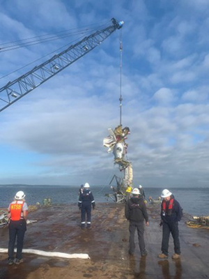
de Havilland DHC-3 (Otter), N725TH, Mutiny Bay (near Freeland, WA), September 4, 2022
The airplane departed from Friday Harbor Seaplane Base (W33), Friday Harbor, WA, about 1450 local time with a destination of Renton Municipal Airport (RNT), Renton, WA. The en route altitude was between 650 and 975 feet above mean sea level and the groundspeed was between 115 and 125 knots. ATC data showed an erratic flight path within the last ten seconds of the flight. Witnesses reported that the airplane was in a near vertical dive before impacting Mutiny Bay and sinking. The debris field was found at a depth of about 190 feet.
About 85% of the airplane was recovered from the sea floor. The horizontal stabilizer trim actuator was found separated where the clamp nut threads into the barrel section. Examination of the threads inside the barrel and the threads on the clamp nut revealed that the two components separated by unthreading (as opposed to being pulled apart in tension). The upper portion of the actuator remained attached to the horizontal stabilizer, and the lower portion remained attached to its mount in the fuselage. A lock ring was used to prevent the barrel and clamp nut from unthreading. The lock ring was not located in the wreckage. Unthreading of the clamp nut and the barrel during flight would result in a free-floating horizontal stabilizer, allowing it to rotate uncontrollably and resulting in a possible loss of airplane control.
NTSB report: AIR-23-01
Cessna 402, Nantucket, Massachusetts, September 13,
2017
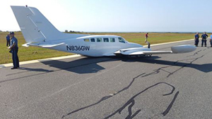
Source: NTSB
A Cessna 402, N836GW, immediately after takeoff executed an emergency landing on the remaining portion of the runway. The pilot stated that after taking off and accelerating, he noticed high nose-down forces that made the aircraft difficult to control. The pilot verified the autopilot was off and attempt to trim out the control forces, but it had no effect. The pilot then performed an emergency gear-up landing on the remaining runway.
The post-accident investigation revealed that the elevator trim tab pushrod assembly had separated from the elevator trim tab actuator. The trim tab push rod was wedged against the rear side of the elevator spar. Investigators found the attach bolt but not the nut and cotter pin were missing. Two weeks prior to the accident the aircraft underwent its annual inspection. During the inspection the aircraft was stripped of the old paint and repainted, which would have required mechanics to remove the right elevator and to disconnect the trim tab push rod from the trim tab actuator. At the time of the inspection, AD 2016-07-24 was overdue and had been subsequently superseded by AD 2016-17-08 which required replacing of hardware to prevent jamming. When the mechanics reinstalled the right elevator, they used the old hardware, not the hardware required by AD 2016-17-08. The NTSB determined the probable cause of this accident was the separation of the pushrod from the elevator trim tab actuator, which rendered controlled flight impossible. Contributing to the separation of the pushrod was the failure of maintenance personnel to properly secure it to the elevator trim tab actuator.
NTSB report: ERA17LA329
Other accidents in the Lessons Learned library related to hardware issues:
China Airlines Flight 120, Boeing 737-800, Okinawa, Japan, August 20, 2007
Following landing and leading-edge slat retraction, a failed portion of the slat track assembly was pressed through the slat track housing and penetrated the right main fuel tank, causing a fuel leak. Fuel that had been leaking from the right-wing tank during taxi and parking was ignited by hot engine surfaces and/or hot brakes and resulted in the aircraft being engulfed in flames.
View library module: China Airlines Flight 120
Sundance Helicopters, Airbus AS-350-B2, Las Vegas, NV, December 7, 2011
The improper reuse of a degraded self-locking nut, the improper or lack of installation of a split pin, and inadequate post-maintenance inspections resulted in the fatal accident of the sight-seeing helicopter. The improper maintenance resulted in the in-flight separation of the servo control input rod from the fore/aft servo and rendered the helicopter uncontrollable.
View library module: Sundance Helicopters, Airbus AS-350-B2
Technical Related Lesson
Assumed failures in a flight control linkage should not result in a catastrophic jammed condition. (Threat Category: System/Component Failure Non-Powerplant)
- Investigators determined that binding or jamming of a flight control surface likely resulted in a deflection that created control forces exceeding the pilot’s ability to counteract them. The jammed trim tab was three times the normal deflection and produced aerodynamic loads that the pilot could not overcome.
- When this aircraft was manufactured, the certification basis allowed linkages to be connected with only a single attachment locking feature. The newer certification rules have changed this design requirement for control surfaces. As a result, aircraft manufacturers should minimize single-point failures in new designs, ensuring robust and reliable systems for continued safe flight and landing.
Common Theme Related Lessons
Although self-locking fasteners provide a high degree of component reliability, human error and other assumed failure conditions may compromise the effectiveness of this safety feature. (Common Theme: Human Error)
- During manufacturing of their piston twin engine aircraft models, the manufacturer made a change from self-locking fasteners to self-locking castellated hardware (dual-locking feature). This change in production practices occurred after the accident aircraft left the factory.
- The manufacturer's selection and usage of proper hardware in rotational joints should have non-friction locking features, such as a self-locking castellated nut and cotter pin, to ensure that critical flight controls cannot become disconnected and cause a loss of control.
- The manufacturer notified and encouraged owners of earlier production airplanes to make the same hardware changes. However, due to no maintenance entry indicating a hardware change and because the hardware was not found at the accident site, investigators concluded that the original self-locking fasteners were still installed on the accident airplane.
For operational safety, a best practice is for aircraft owners and regulators to carefully evaluate and determine which service letters and bulletins should be implemented as part of maintenance regimen to ensure operational safety. (Common Theme: Organizational Lapses)
- FAA regulations state that it is the responsibility of the owner or pilot in command to determine if the aircraft is in a condition for safe flight. It is also the responsibility of regulators to determine if, in the absence of the incorporation of the service letters and bulletins, an unsafe condition exists. Issuance of an AD would be appropriate in the case where an unsafe condition is determined. Operators need to address service letters, bulletins, and ADs applicable to the aircraft and identify those that should be implemented and recorded.
- Publishing service letters or service bulletins do not guarantee instructions are followed, even if the manufacturer classifies them as mandatory. Owners should make this assessment independent of the FAA. There was no indication that the owner implemented the service publications; however, failure of the trim tab attachment may have been prevented had the owner replaced the self-locking nut with a self-locking castellated nut as the service letter recommended. Compliance with service documents may reduce safety of flight risk.